Page 24
© Yanmar 2008
Electronic Control System:
Operation Manual for SY Series Engines with GEN III Controls
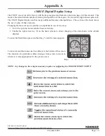
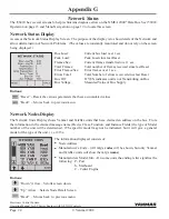
Buttons:
“Down” Arrow – Scrolls screen down.
“Up” Arrow – Selects Node Detail Screen
“Back” – Moves back to previous menu
Buttons:
“Reset” – Resets the various parameters that have accumulated values
“Back” – Moves back to previous menu
Appendix G
The i5601E has several screens to help technicians diagnose errors on the NMEA 2000
®
Data Bus. See i5601E
Operation on page 15 and Menu Navigation on page 19 to locate this screen.
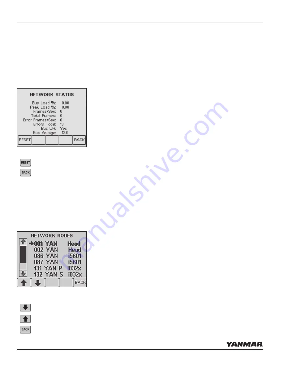
Network Status Display
Accesses the Network Status Display Screen. The purpose of the display is to show details of the Network and
allow determination of Network Problems. (The values are constantly monitored and do not rely on the screen
being displayed.)
Network Nodes Display
The Network Units Display shows Yanmar and Teleflex units that have claimed an address on the bus. From
the information in the claimed message name (Device Class, Function, and Instance Fields) the type of Model
number of the unit will be determined. (The specific model may not be indicated, but it will give a general
model of the type of the unit.) i.e. i813x.
The information displayed consists of:
•
Node Address
•
Manufacturer’s Code - (All mfg’s
codes
will be shown, but only Yanmar
and Teleflex units will show the mfg’s
name
)
•
Manufacturers Model Info - On some units the ending letter signifies the
following: P - Port
S - Starboard
C - Center Engine
Bus Load:
Current bus load over 1 sec
Peak Load:
Peak Load since last Reset
Frames/Sec:
Current frames transferred over 1 sec
Total Frames:
Total number of frames received since last Reset
Error Frames/Sec:
Error frames over 1 sec
Errors Total:
Total Number of errors received since last Reset
Bus Off
If YES, indicates unit is not Transmitting on Bus
Bus Voltage:
Measured Value of Bus Supply
Network Status
Summary of Contents for i8350
Page 28: ......

