Page 6
© Yanmar 2008
Electronic Control System:
Operation Manual for SY Series Engines with GEN III Controls
Various features of the electronic control system have been selected and set as part of the installation. They can
be checked in Appendix C. They include:
•
Max Throttle Amount in Split Range Throttle (SRT)
•
Shift Delays
•
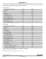
Type of Sync (Power Train or Cruise)
•
Station Protection
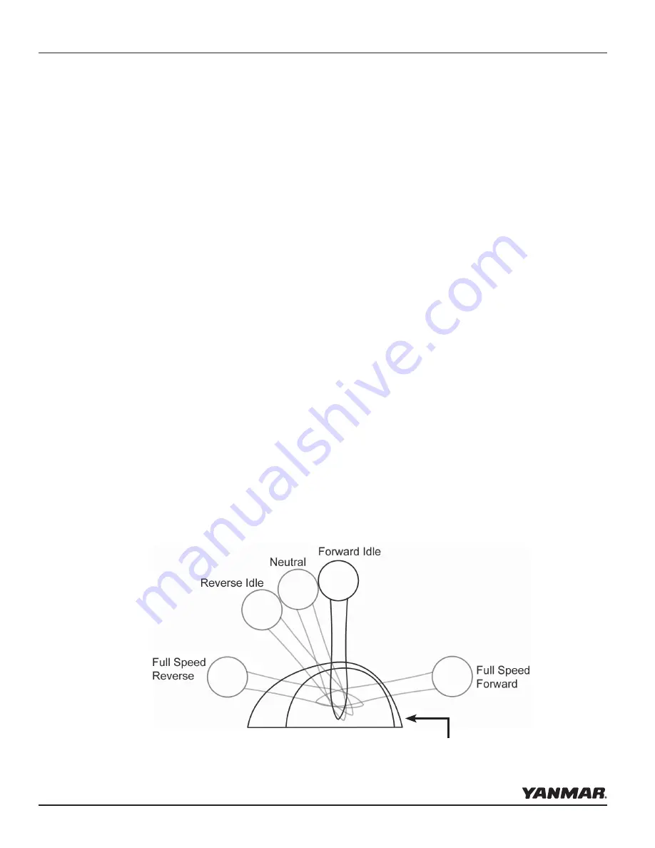
1. Before starting the engines for the first time, take a moment to familiarize yourself with the shift and throttle
controls. With the engines not running, move the control levers over the full range until you are familiar with
the feel. Note that the detent pressure and drag can be adjusted using the adjusting screw on the front surface
of the control head. The top screw sets the detent pressure; the lower screw sets the drag.
2. Place the control levers in neutral and turn the ignition switches to the
ON position --
but do not start the
engine.
The green control head light will illuminate.
a. Check to see if the green light on the control head is solid or flashing. If solid, proceed to the next step.
If flashing, push the Select button to select the head. Position the control lever to neutral and the yellow
light will now come on.
The Shift & Throttle Control Head selects the gear positions and the throttle settings. The Control Head has
several lights that confirm modes of operation and display warnings, if present. Buttons enable engine RPM
synchronization and shift disconnect as well as setting the brightness of the lights.
Other control configurations with the same functions but different form factors may be used. Refer to the
supplemental material included with those controls.
shift & throttle Control Head functions
The most common Shift and Throttle Control Head comes with a dual function, single lever control. A single
lever control initiates both shifting and throttle for a single engine.
first time Control operation
Start Up
note that the detent pressure and drag can be adjusted using the
adjusting screw on the front surface of some control heads.
Summary of Contents for i8350
Page 28: ......


