background image

BEFORE YOU OPERATE

JH Series Operation Manual

51

Priming the Fuel System

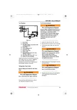
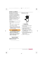
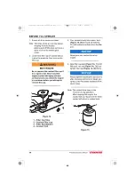
Bleeding the fuel filter

An automatic bleeding device is installed 
on the fuel filter. Therefore an air bleed 
screw is not required.

1. Push up and down on the priming 

pump to bleed the fuel filter. (approx. 60 
times)

2. When you begin to feel resistance, 

bleeding is complete.

NOTICE

Never use the starter motor to crank the 
engine in order to prime the fuel system. 
This may cause the starter motor to 
overheat and damage the coils, pinion 
and/or ring gear.

ENGINE OIL

Engine Oil Specifications 

Using engine oil that does not meet or 
exceed the following guidelines or 
specifications may cause seizure of parts, 
abnormal wear and shorten engine life.

Service Categories

Use an engine oil that meets or exceeds 
the following guidelines and classifications:

• API Service Categories CD, CF, CF-4, 

CI and CI-4.

• SAE Viscosity: 10W-30, 15W-40. Engine 

oil 10W-30 and 15W-40 can be used 
throughout the year.

NOTICE

• Be sure the engine oil, engine oil storage 

containers and engine oil filling 
equipment are free of sediment or water.

• Change the engine oil after the first 50 

hours of operation and then at every 250 
hours thereafter.

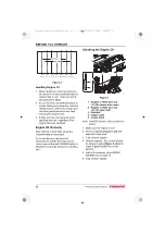
• Select the oil viscosity based on the 

ambient temperature where the engine 
is being operated. See the SAE Service 
Grade Viscosity Chart 

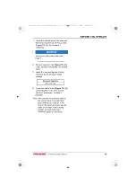
(Figure 5)

.

• YANMAR does not recommend the use 

of engine oil “additives”.

3JH40_4JH45_4JH57_4JH80_4JH110_EN_OPM.book  51 ページ  2022年9月22日 木曜日 午後6時17分

Summary of Contents for JH Series

Page 1: ...OPERATION MANUAL English en MARINE ENGINE JH 3JH40 4JH45 4JH57 4JH80 4JH110...

Page 2: ...CO LTD in Japan the United States and or other countries All Rights Reserved No part of this publication may be reproduced or used in any form by any means graphic electronic or mechanical including p...

Page 3: ...IONS 11 New Engine Break In 12 COMPONENT IDENTIFICATION 13 Right Side Viewed from Flywheel 3JH40 13 Left Side Viewed from Flywheel 3JH40 13 Right Side Viewed from Flywheel 4JH45 4JH57 14 Left Side Vie...

Page 4: ...ifications 51 Engine Oil Viscosity 52 Checking the Engine Oil 52 ADDING ENGINE OIL 53 MARINE GEAR OR SAIL DRIVE OIL 53 Marine Gear Oil Specifications 53 Sail Drive Oil Specifications 53 Checking Marin...

Page 5: ...If the Engine Fails to Start 75 Starting at Low Temperatures 75 After the Engine has Started 75 WARM UP MODE SHIFT DISCONNECT 76 THROTTLE AND SHIFT CONTROL 77 Neutral 77 Forward 77 Reverse 77 Forward...

Page 6: ...ce of Daily Checks 107 Keep a Log of Engine Hours and Daily Checks 107 YANMAR Replacement Parts 107 Tools Required 107 Consult Your Authorized YANMAR Marine Dealer or Distributor for Help 107 Tighteni...

Page 7: ...gine 152 3JH40 Marine Gear or Sail Drive 153 4JH45 Engine 154 4JH57 Engine 155 4JH45 4JH57 Marine Gear or Sail Drive 156 4JH80 Engine 157 4JH110 Engine 158 4JH80 4JH110 Marine Gear or Sail Drive 159 S...

Page 8: ...TABLE OF CONTENTS vi JH Series Operation Manual This Page Intentionally Left Blank 3JH40_4JH45_4JH57_4JH80_4JH110_EN_OPM book vi...

Page 9: ...rocedures Keep this Operation Manual in a convenient place for easy access If this Operation Manual is lost or damaged order a new one from your authorized YANMAR Marine dealer or distributor Make sur...

Page 10: ..._____________ Dealer _________________________________________________________________ Dealer Phone ___________________________________________________________ To Register Your YANMAR Engine 1 Visit h...

Page 11: ...part and label at the same time DANGER Indicates a hazardous situation which if not avoided will result in death or serious injury WARNING Indicates a hazardous situation which if not avoided could re...

Page 12: ...tional reminders for safe operating and maintenance techniques Consult authorized YANMAR Marine dealer or distributor for additional training During Operation and Maintenance WARNING The safety messag...

Page 13: ...othing gloves work shoes and eye and hearing protection as required by the task at hand Sudden Movement Hazard Never operate the engine while wearing a headset to listen to music or radio because it w...

Page 14: ...events unexpected downtime reduces the number of accidents due to poor engine performance and helps extend the life of the engine Consult authorized YANMAR Marine dealer or distributor if you need to...

Page 15: ...ust of the non running engine s This water could cause seizure of the non running engine s Consult authorized YANMAR Marine dealer or distributor for a complete explanation of this condition If you ha...

Page 16: ...nd 4JH80 110 series marine engines Figure 13JH40 Engine Figure 1 1 Part Number 128296 07350 2 Part Number 128171 07150 3 Part Number 128990 07270 4 Part Number 196630 12980 WARNING 128296 07350 128990...

Page 17: ...umber 128296 07350 2 Part Number 128171 07150 3 Part Number 128990 07270 4 Part Number 196630 12980 WARNING 128296 07350 128990 07270 2 CAUTION Overcranking engine with water lift muffler can cause da...

Page 18: ...2 Part Number 128990 07270 3 Part Number 128171 07150 4 Part Number 120650 07060 5 Part Number 196630 12980 056978 03X01 WARNING 128296 07350 128990 07270 3 CAUTION Overcranking engine with water lif...

Page 19: ...uipment attached to the engine should be easy to use and accessible for service To handle the drive equipment propulsion systems including the propeller and other inboard equipment always observe the...

Page 20: ...e piston rings when operating at low speeds for long periods this will interfere with proper movement of the rings and the engine oil consumption may increase Low idle speed does not allow break in of...

Page 21: ...6 Engine oil filler cap 7 Fuel supply pump 8 Engine oil filter 9 Engine oil cooler 10 Marine gear KM35P 11 Marine gear oil dipstick 12 Shift lever Left Side Viewed from Flywheel 3JH40 Figure 2 13 Coo...

Page 22: ...oil filler cap 7 Fuel supply pump 8 Engine oil filter 9 Engine oil cooler 10 Marine gear KM4A1 11 Shift lever 12 Marine gear oil dipstick Left Side Viewed from Flywheel 4JH45 4JH57 Figure 4 13 Coolant...

Page 23: ...il filler cap 8 Fuel supply pump 9 Engine oil filter 10 Engine oil cooler 11 Marine gear KMH4A 12 Marine gear oil dipstick 13 Shift lever Left Side Viewed from Flywheel 4JH80 4JH110 Figure 6 14 Coolan...

Page 24: ...m cover Figure 7 The marine gear nameplate Figure 8 is attached to the marine gear Check the marine gears model gear ratio oil used and serial number Figure 8 The sail drive nameplate Figure 9 is atta...

Page 25: ...water also cools the marine gear oil and intake air depending on model through the cooler s in an open circuit Coolant pump The centrifugal water pump circulates coolant inside the engine The circulat...

Page 26: ...crease in engine speed WARNING Replacing the ECU involves migrating the fuel injection data to the existing ECU to the new unit Be sure to consult your local YANMAR dealer before replacing the ECU Fai...

Page 27: ...he high pressure fuel from the rail to the engine combustion room after receiving a signal from the ECU in the most appropriate injection timing injection volume injection ratio number of injection an...

Page 28: ...to the engine control lever and marine gear Instrument Panel Optional Equipment and Functions The instrument panel is located in the cockpit The following instruments enable you to start or stop the e...

Page 29: ...ture and oil pressure display B25 C35 Type panels have a digital LCD screen inside the tachometer C35 Type panels have an electric gauge with a needle Instrument Function Tachometer Shows engine rotat...

Page 30: ...itches push buttons Control panel switches All switches are push buttons 042563 02X00 4 2 1 3 Start switch Pushing this switch operates the starter and starts the engine Stop switch Pushing this switc...

Page 31: ...at temperatures exceeding the maximum limit will result in damage and seizure Check the load and troubleshoot the cooling system Engine Oil Low Pressure Indicator and Alarm When the engine oil pressu...

Page 32: ...ght Press the left button continuously and the digits of the LCD start flashing In this condition press the left button to increase the brightness Press the right button to decrease the brightness The...

Page 33: ...to see all the applying trouble codes Look up the codes in the Failsafe Diagnosis Functional Specification Chart on page 142 and consult your authorized YANMAR Marine dealer or distributor for repair...

Page 34: ...etting the temperature and pressure units The display says UNIT Next press the right button to select Metric units C BAR The display says METRIC Press the left button to switch to Imperial units F PSI...

Page 35: ...pe of the gauges Change the type by pressing the left button Press the right button to select the type Press the left button and go to the next screen dISPLAY There are four types of fuel level gauge...

Page 36: ...e next screen ENG Ld Setting of the next indicator Repeat the same procedure to set other indicators When RETURN is indicated on the screen press the right button to exit the dISPLAY mode Press the le...

Page 37: ...dicates JH When JH is indicated on the screen press the right button to return to ENGINE When ENGINE is indicated press the left button to go to EXIT Press the right button when EXIT is shown on the s...

Page 38: ...Hour meter Water temperature Backlight Engine oil pressure Battery voltage Hour meter Throttle position Engine load Fuel flow rate Intake air pressure Fuel temperature These parameters are indicated...

Page 39: ...fter Engine Start After engine start make sure that the warning devices operate correctly and according to After start in the below table All alarm lamps turn off The above check tells you whether the...

Page 40: ...d to the panel power supply can be taken off Figure 21 Refer to the Service Manual The maximum current of this output terminal is 3 A Fuse capacity Do not use a current higher than 3 A For the content...

Page 41: ...ction of the boat ahead or astern and also acts as an accelerator by increasing engine speed as the lever is pushed further in FORWARD or REVERSE directions When the handle is pulled out Figure 23 1 t...

Page 42: ...th the instructions in this manual or the system is modified in any way YANMAR will not be responsible for any warranty failures in the operation of the system or the vessel utilizing the system YANMA...

Page 43: ...or and ask for diagnostics Diag Codes Screen Figure 13 Figure 27 Alarm Indicator Functions The alarm indicators and buzzer are activated when sensors detect an abnormality during engine operation The...

Page 44: ...levant icon If there are multiple items execute with the ENTER button after selecting with the buttons Adjusting Brightness Press the button Display the brightness adjustment screen and adjust brightn...

Page 45: ...ch Use this switch only in an emergency NOTICE Under normal circumstances do not use the Emergency stop switch to stop the engine The engine shuts down suddenly when the Emergency stop switch is press...

Page 46: ...ith the instructions in this manual or the system is modified in any way YANMAR will not be responsible for any warranty failures in the operation of the system or the vessel utilizing the system YANM...

Page 47: ...39 NOTICE Compass safety distance for Shift and Throttle Control Head Follow the compass safe distances to prevent interference to a magnetic compass Standard compass Steering compass 0 45 m 0 30 m 3J...

Page 48: ...or and ask for diagnostics Diag Codes Screen Figure 18 Figure 33 Alarm Indicator Functions The alarm indicators and buzzer are activated when sensors detect an abnormality during engine operation The...

Page 49: ...If there are multiple items execute with the ENTER button after selecting with the buttons Adjusting Brightness Press the button Display the brightness adjustment screen and adjust brightness with the...

Page 50: ...he minimum and maximum brightness as required The brightness is adjusted in 8 steps Figure 22 Figure 38 122766 00X00 OIL PRESSURE COOLANT TEMP 0 0 0 MAIN MENU Alarms DIAGs Display Engine speed Monitor...

Page 51: ...e this switch only in an emergency Figure 24 Figure 40 NOTICE Under normal circumstances do not use the Emergency stop switch to stop the engine The engine shuts down suddenly when the Emergency stop...

Page 52: ...PRODUCT OVERVIEW 44 JH Series Operation Manual This Page Intentionally Left Blank 3JH40_4JH45_4JH57_4JH80_4JH110_EN_OPM book 44...

Page 53: ...of the Operation Manual describes the diesel fuel engine oil and engine coolant specifications and how to replenish them SAFETY PRECAUTIONS Before performing any operations within this section review...

Page 54: ...t the minimum specifications for the country in which they are used In Europe biodiesel fuels must comply with the European Standard EN590 2009 EN14214 In the United States biodiesel fuels must comply...

Page 55: ...our engine Additional Technical Fuel Requirements The fuel cetane number should be 45 or higher The sulfur content must not exceed 0 5 by volume Less than 0 05 is preferred Especially in U S A and Can...

Page 56: ...ld cause sparks and ignite fuel vapors 1 Water and dust in the fuel may cause engine failure When fuel is stored be sure that the inside of the storage container is clean and dry and that the fuel is...

Page 57: ...operly To fill the fuel tank WARNING Fire and Explosion Hazard Operate bilge ventilation blowers for a minimum of 5 minutes to purge fumes from engine compartment after refueling Never operate bilge b...

Page 58: ...and draining the fuel filter water separator or replacing a fuel system component WARNING Fire and Explosion Hazard Diesel fuel is flammable and explosive under certain conditions Failure to comply c...

Page 59: ...lowing guidelines or specifications may cause seizure of parts abnormal wear and shorten engine life Service Categories Use an engine oil that meets or exceeds the following guidelines and classificat...

Page 60: ...at temperatures outside the limits shown consult your authorized YANMAR dealer or distributor for special lubricants or starting aids Checking the Engine Oil Figure 6 1 Engine oil filler port cap On t...

Page 61: ...the oil level between upper and lower lines on the oil cap dipstick 4 Hand tighten the filler port cap securely MARINE GEAR OR SAIL DRIVE OIL Marine Gear Oil Specifications Use marine gear oil that m...

Page 62: ...The oil level should be between upper Figure 7 3 and lower Figure 7 4 lines on the dipstick 6 Screw in the dipstick Adding Marine Gear Oil 1 Make sure the engine is level 2 Remove the filler cap Figur...

Page 63: ...water especially when operating in cold weather Never use hard water Water should be clean and free from sludge or particles Without LLC cooling performance will decrease due to scale and rust in the...

Page 64: ...H40 Figure 8 1 Coolant drain cock Cylinderblock Figure 1 Figure 9 2 Coolant pump 3 Coolant tank Heat exchanger 4 Coolant drain cock Coolant tank Heat exchanger 5 Seawater pump Drain from pump cover 1...

Page 65: ...pump Drain from pump cover 4JH80 4JH110 Figure 12 1 Turbocharger 2 Coolant drain cock Cylinderblock 3 Marine gear oil cooler KMH4A 4 Seawater drain cock Marine gear oil cooler Figure 3 Figure 13 5 Coo...

Page 66: ...Tabs 2 Coolant Filler Cap 3 Filler Port Notches 4 Coolant Tank 3 Pour coolant slowly into coolant tank Figure 14 4 to avoid air bubbles Fill until coolant overflows from the filler port NOTICE Never...

Page 67: ...all filler cap and tighten it firmly Failure to do so will cause water leakage 8 Check the rubber hose Figure 15 1 connecting the reservoir to coolant tank heat exchanger Replace if damaged Note If th...

Page 68: ...BEFORE YOU OPERATE 60 JH Series Operation Manual This Page Intentionally Left Blank 3JH40_4JH45_4JH57_4JH80_4JH110_EN_OPM book 60...

Page 69: ...on Manual describes the procedures for starting the engine checking engine performance during operation and shutting down the engine SAFETY PRECAUTIONS Before performing any operations within this sec...

Page 70: ...e you continue to operate the engine If the vessel is equipped with a water lift water lock muffler excessive cranking could cause seawater to enter the cylinders and damage the engine If the engine d...

Page 71: ...ng the Engine 1 Open the seacock if equipped 2 Open the fuel tank cock 3 Put remote control handle in NEUTRAL Note Safety equipment should make it impossible to start the engine in any other position...

Page 72: ...l water intake valve to avoid filling the muffler with water Crank for 10 seconds at a time until the engine starts When the engine does start stop the engine immediately and turn off the power switch...

Page 73: ...Identify the cause and repair NOTICE The engine will seize if it is operated when seawater discharge is too small or if load is applied without any warming up operation For troubleshooting assistance...

Page 74: ...h the engine at idle When sailing set the remote control handle in NEUTRAL Not doing so WILL introduce slippage or any damage and void your warranty In case that the marine gear can not be shifted by...

Page 75: ...ine speed Operate the engine at about 100 min 1 lower than the full throttle engine speed Note If the engine is in the first 50 hours of operation see New Engine Break In on page 12 Always be on the l...

Page 76: ...or any problems Is there sufficient diesel fuel in the diesel fuel tank Replenish diesel fuel before leaving the dock to avoid running out of fuel during operation When operating the engine at low spe...

Page 77: ...push the power switch off NOTICE Continue to hold the stop switch in until the engine is completely stopped If the switch is released before the engine has completely stopped it may restart If the en...

Page 78: ...low 0 C 32 F Engine Auxiliary Stop Switch NOTICE Never use the auxiliary stop switch for a normal engine shutdown Use this switch only when stopping the engine suddenly in an emergency Figure 3 Figure...

Page 79: ...u can restart the engine but an alarm may be set up when the power switch is turned on Unless you are in an emergency situation in order to release above alarm turn off the power switch and wait 6 sec...

Page 80: ...sure to turn the Power switch ON Figure 6 Figure 8 5 If the Sys on by ID has been set enter the password into the display 6 Press the control head SEL switch Wait until thedisplay shows the engine dat...

Page 81: ...and for Single Station the SEL lamp will come on 2 Pressing the Engine START STOP switch when the SEL lamp is flashing allows the station to be selected as the engine is started 3 The engine will not...

Page 82: ...ted Sys on by ID and Start by ID cannot be disabled and it is required to enter the Owner ID at each time After entering the ID and verification if you don t operate for 10 seconds the entry becomes i...

Page 83: ...open the seacock and restart the engine Operate the engine normally Air Bleeding the Fuel System after Starting Failure If the engine does not start after several attempts there may be air in the fuel...

Page 84: ...ize if it is operated when seawater discharge is too small or if load is applied without any warming up operation WARM UP MODE SHIFT DISCONNECT 1 Move the remote control handle to the N Neutral positi...

Page 85: ...Move the handle toward F forward to the forward side notch position The engine will remain idling Moving the handle forward further will increase the engine speed Reverse Move the handle toward R rev...

Page 86: ...e can arise if the engine is operated for a long time under overloaded conditions with the control handle in the full throttle position maximum engine speed position exceeding the continuous rated out...

Page 87: ...or any problems Is there sufficient diesel fuel in the diesel fuel tank Replenish diesel fuel before leaving the dock to avoid running out of fuel during operation When operating the engine at low spe...

Page 88: ...is stopped The engine will restart 5 Wait 6 seconds or more before turning the battery switch off for secure system settle down NOTICE Do not turn the battery switch off before turning the power switc...

Page 89: ...down you allow the engine to idle without load for 5 minutes This will allow the engine components that operate at high temperatures such as the turbo charger and exhaust system to cool slightly befor...

Page 90: ...arm is set In order to release above alarm turn off the power switch and wait 6 seconds before turning the power switch on again 7 Turn the battery switch off for engine and engine control system 8 Cl...

Page 91: ...etime to restart Note 1 The Emergency Stop switch should only be used in emergencies Use the Engine START STOP switch to stop the engine normally 2 The engine cannot be started while the Emergency Sto...

Page 92: ...y anti clockwise first Be sure to lower the engine speed by turning the sub throttle volume fully to anti clockwise before stopping the engine The shift switch where is behind the left cover of Backup...

Page 93: ...l Tank on page 49 Close seawater cock s If there is a risk of freezing check that the cooling system contains enough coolant See Engine Coolant Specifications on page 55 If there is a risk of freezing...

Page 94: ...l come on or flash To use the Engine START STOP switch be sure to turn the Power switch ON Figure 19 Figure 25 5 If the Sys on by ID has been set enter the password into the display 6 Press the contro...

Page 95: ...h and for Single Station the SEL lamp will come on 2 Pressing the Engine START STOP switch when the SEL lamp is flashing allows the station to be selected as the engine is started 3 The engine will no...

Page 96: ...ted Sys on by ID and Start by ID cannot be disabled and it is required to enter the Owner ID at each time After entering the ID and verification if you don t operate for 10 seconds the entry becomes i...

Page 97: ...s displayed the switch panel lamp blinks Figure 28 Figure 34 OIL PRESSURE COOLANT TEMP 0 0 0 MAIN MENU Alarms DIAGs Display Engine speed Monitor settings Synchro Utility Station protect Sys on by ID S...

Page 98: ...s the ENTER button with the icon left side on the top highlighted Figure 32 Figure 38 142303 00X Move the keys closer to the blinking key mark on the switch panel Up to 10 keys can be registered Key 2...

Page 99: ...larm YANMAR E key View ON OFF 142306 00EN OIL PRESSURE COOLANT TEMP 0 0 0 MAIN MENU Alarms DIAGs Display Engine speed Monitor settings Synchro Utility Station protect Sys on by ID Start by ID Owner ID...

Page 100: ...38 Figure 44 3 Hold the key fob in front of the lamp while it is blinking Figure 39 Figure 45 4 The Power switch lamp will come on Figure 40 Figure 46 In the case of two or more engines once the key...

Page 101: ...open the seacock and restart the engine Operate the engine normally Air Bleeding the Fuel System after Starting Failure If the engine does not start after several attempts there may be air in the fuel...

Page 102: ...hen seawater discharge is too small or if load is applied without any warming up operation WARM UP MODE SHIFT DISCONNECT 1 Move the remote control handle to the N Neutral position The NEUTRAL lamp wil...

Page 103: ...firmly into either the forward or reverse position Forward Move the handle toward F forward to the forward side notch position The engine will remain idling Moving the handle forward further will inc...

Page 104: ...ne is operated for a long time under overloaded conditions with the control handle in the full throttle position maximum engine speed position exceeding the continuous rated output engine speed Operat...

Page 105: ...or any problems Is there sufficient diesel fuel in the diesel fuel tank Replenish diesel fuel before leaving the dock to avoid running out of fuel during operation When operating the engine at low spe...

Page 106: ...is stopped The engine will restart 5 Wait 6 seconds or more before turning the battery switch off for secure system settle down NOTICE Do not turn the battery switch off before turning the power switc...

Page 107: ...at when shutting the engine down you allow the engine to idle without load for 5 minutes This will allow the engine components that operate at high temperatures such as the turbo charger and exhaust s...

Page 108: ...f the alarm is set In order to release above alarm turn off the power switch and wait 6 seconds before turning the power switch on again 7 Turn the battery switch off for engine and engine control sys...

Page 109: ...estart Note 1 The Emergency Stop switch should only be used in emergencies Use the Engine START STOP switch to stop the engine normally 2 The engine cannot be started while the Emergency Stop switch i...

Page 110: ...y anti clockwise first Be sure to lower the engine speed by turning the sub throttle volume fully to anti clockwise before stopping the engine The shift switch where is behind the left cover of Backup...

Page 111: ...l Tank on page 49 Close seawater cock s If there is a risk of freezing check that the cooling system contains enough coolant See Engine Coolant Specifications on page 55 If there is a risk of freezing...

Page 112: ...ENGINE OPERATION 104 JH Series Operation Manual This Page Intentionally Left Blank 3JH40_4JH45_4JH57_4JH80_4JH110_EN_OPM book 104...

Page 113: ...ty section on page 3 WARNING Crush Hazard If the engine needs to be transported for repair have a helper assist you attach it to a hoist and load it on a truck The engine lifting eyes are engineered t...

Page 114: ...lly start the engine and not realize you are servicing it Shock Hazard Always turn off the battery switch if equipped or disconnect the negative battery cable before servicing the equipment Always kee...

Page 115: ...s Make it a habit to perform daily checks before the start of each operating day See Daily Checks on page 116 Keep a Log of Engine Hours and Daily Checks Keep a log of the number of hours the engine i...

Page 116: ...d Apply 80 torque when tightened to aluminum alloy When lock adhesive is applied decide separately When seal washer applied torque is 34 5 N m 25 1 3 7 ft lb Bolt Diameter x Pitch mm M6x1 0 M8x1 25 M1...

Page 117: ...M8 x 1 25 Without oil 13 5 0 5 10 0 0 4 Supply pump gear nut M18 x 1 5 Without oil 80 0 5 0 59 0 3 7 Retainer bolt for Flywheel speed sensor M6 x 1 0 Without oil 8 0 2 0 5 9 1 5 Retainer bolt for Cam...

Page 118: ...ENANCE SCHEDULE on page 113 and the PERIODIC MAINTENANCE PROCEDURES on page 116 EPA Requirements for USA and Other Applicable Countries The EPA emission regulation is applicable only in the USA and ot...

Page 119: ...mum of cetane No 45 The lubricating oil should be API Service Categories CD CF CF 4 CI and CI 4 Be sure to perform inspections as outlined in PERIODIC MAINTENANCE PROCEDURES on page 116 and keep a rec...

Page 120: ...ctions for the proper installation and location of the required sample port in addition to those specified above in the quoted federal regulation are follows 1 The connection should be located as far...

Page 121: ...he warranty coverage on your engine Consult authorized YANMAR Marine dealer or distributor for assistance when checking items marked with a Check or Clean Replace Consult your authorized YANMAR Marine...

Page 122: ...level in the battery Adjust the tension of the alternator V ribbed belt or replace V ribbed belt Initial 50 Check the wiring connectors Engine Cylinder Head and Block Check for leakage of fuel engine...

Page 123: ...certified as EPA CI marine engines Inspection and Maintenance of Emission Related Parts of Marine CI Engines Note YANMAR recommends that the inspection and maintenance items shown above be performed...

Page 124: ...uel leak with your hands WARNING Always use a piece of wood or cardboard Have your authorized YANMAR Marine dealer or distributor repair any damage 3 Check for engine coolant leaks 4 Check for damaged...

Page 125: ...perating the start switch on the instrument panel check that there is no alarm message on the display and the alarm indicators work normally See CONTROL EQUIPMENT on page 20 Preparing Fuel Oil and Coo...

Page 126: ...e oil drain pump if equipped and pump out the oil For easier draining remove the engine oil fill cap Dispose of used oil properly NOTICE Prevent dirt and debris from contaminating engine oil Carefully...

Page 127: ...h kerosene or clean diesel fuel c Hold the filter in place with the coil spring Figure 3 3 and insert into the case Install a new O ring Figure 3 4 in the side cover d Install side cover and tighten s...

Page 128: ...any defects are found replace the V ribbed belt 2 Check that the belt fits properly in the ribbed grooves NOTICE Confirm by hand that the belt has not slipped out of the grooves on the bottom of the...

Page 129: ...gure 7 7 for the remote control cable and adjust 2 Adjust the low speed stop position Figure 7 6 first and then adjust the high speed stop position Figure 7 2 with the adjustment screw on the remote c...

Page 130: ...t the position of the cable Adjusting Propeller Shaft Alignment The flexible engine mounts are compressed slightly during initial engine operation and may cause misalignment between the engine and the...

Page 131: ...ure 4 Figure 11 1 Filter element 2 Drain plug 3 Cover fire resistant 4 Clamp screw NOTICE If the fuel filter water separator is positioned higher than the fuel level in the fuel tank water may not dri...

Page 132: ...ly flush the affected area with a large amount of clean water and obtain prompt medical treatment NOTICE Never turn off the battery switch if equipped or short the battery cables during operation Dama...

Page 133: ...Changing the Marine Gear Oil and Replacing Marine Gear Oil Filter Element If Equipped Checking or Replacing the Seawater Impeller Changing the Coolant Cleaning the Intake Silencer Air Cleaner Element...

Page 134: ...art of the fuel pre filter water separator to protect the water alarm switch 3 Attach a tube to the drain plug 4 Loosen the drain plug and drain the fuel from the drain plug 5 Disconnect the electrica...

Page 135: ...Gear Oil Filter Element if equipped See Changing the Marine Gear Oil and Replacing the Marine Gear Oil Filter Element if equipped on page 127 Checking or Replacing Seawater Pump Impeller 1 Loosen side...

Page 136: ...impeller 3 Turn the jack screw Figure 16 B clockwise to remove the impeller from the pump body Figure 17 Figure 18 Note When replacing a used impeller with a new one the impeller must have an M18x1 5...

Page 137: ...occur flush eyes and wash immediately with clean water Change the coolant every year NOTICE Never mix different types and or colors of coolants Discard old coolant in an approved manner according to...

Page 138: ...r Figure 64JH45 4JH57 Figure 21 1 Coolant drain cock Cylinderblock 2 Marine gear oil cooler KM4A1 3 Seawater drain cock Marine gear oil cooler Figure 22 4 Coolant pump 5 Coolant tank Heat exchanger 6...

Page 139: ...he drain cocks 4 Fill coolant tank and reservoir with appropriate coolant See Engine Coolant Specifications on page 55 and Checking and Adding Coolant on page 56 Cleaning the Intake Silencer Air Clean...

Page 140: ...NMAR Marine dealer or distributor Tightening All Major Nuts and Bolts See Tightening Fasteners on page 108 or consult authorized YANMAR Marine dealer or distributor Perform the following maintenance e...

Page 141: ...ing or Replacing Seawater Pump Impeller on page 127 Cleaning and Checking the Seawater Passages After prolonged use clean the seawater passages to remove trash scale rust and other contaminants that c...

Page 142: ...on on page 119 Adjusting Intake Exhaust Valve Clearance Consult authorized YANMAR Marine dealer or distributor Checking the Remote Control Cable Operation Consult authorized YANMAR Marine dealer or di...

Page 143: ...ow stop the engine immediately Identify the cause and repair Is the smoke color normal The continuous emission of black exhaust smoke indicates engine overloading This shortens the engines life and sh...

Page 144: ...engine near maximum speed while underway This will generate higher exhaust temperatures which will help clean out hard carbon deposits maintain engine performance and prolong the life of the engine T...

Page 145: ...tarter Increase the cable size or shorten Insufficient battery charge Charge No fuel injection Incomplete priming of fuel system Carry out sufficient priming Clogged fuel inlet filter Replace Fuel lev...

Page 146: ...l pipe conduct priming Fuel cock closed Inspect and repair as necessary Clogged fuel filter Replace Broken fuel pipe Replace Failure of fuel supply pump Replace Other Moving parts seized Disassemble a...

Page 147: ...Clogged air cleaner Clean Dirty compressor side Clean Clogged turbine nozzle Clean Damaged bearing Replace Other Improper fuel Replace with correct fuel Clogged exhaust duct Clean Seized or overheate...

Page 148: ...compressor Clean Entrapment of foreign matter at turbine entrance Repair or replace Rapid change in load surging Stabilize the load or replace turbine nozzle Quick contamination of engine oil Gas trap...

Page 149: ...ndicators does not go out Sensor switch is faulty Consult authorized YANMAR Marine dealer or distributor Battery low charge indicator does not go out during operation V ribbed belt is loose or broken...

Page 150: ...28 4 4 Main Analog Throttle Sensor 1 Error Low Range Main Analog Throttle Sensor 2 Error Low Range Both signal of the dual throttle sensor are out of limit AC1 ERR AC2 ERR P0123 P0122 91 28 3 3 Main A...

Page 151: ...2798 6 Injector Bank2 Short Circuit FUEL P1151 522329 0 Water In Fuel Condition CHK ENG P1192 100 4 Oil Pressure Switch Open Circuit Suspicious Broken sensor or wire poor connection OIL PRS P1198 100...

Page 152: ...Injector 1 QR Code Data Error Input failure of the injector correction value CHK ENG P1649 523463 13 Injector 2 QR Code Data Error CHK ENG P1650 523464 13 Injector 3 QR Code Data Error CHK ENG P1651 5...

Page 153: ...1010 521238 3 Tank1 level sensor HI range C1010 521238 4 Tank1 level sensor LO range C1011 521239 3 Tank2 level sensor HI range C1011 521239 4 Tank2 level sensor LO range C1051 521240 3 Rudder angle s...

Page 154: ...lling function come to be unavailable P0120 91 4 MAIN THROTTLE SENSOR L RANGE B1020 91 13 THROTTLE CALIBRATION INCONSISTENCY Station change function come to be unavailable B1043 523768 12 HELM ECU EEP...

Page 155: ...e of the engine it may freeze and damage parts of the cooling system when the ambient temperature is below 0 C 32 F PREPARE ENGINE FOR LONG TERM STORAGE Note If the engine is close to a periodic maint...

Page 156: ...igure 13JH40 Figure 1 1 Coolant drain cock Cylinderblock Figure 2 2 Coolant pump 3 Coolant tank Heat exchanger 4 Coolant drain cock Coolant tank Heat exchanger 5 Seawater pump Drain from pump cover 1...

Page 157: ...ump Drain from pump cover Figure 44JH80 4JH110 Figure 5 1 Turbocharger 2 Coolant drain cock Cylinderblock 3 Marine gear oil cooler KMH4A 4 Seawater drain cock Marine gear oil cooler Figure 5 Figure 6...

Page 158: ...ain cock on the air cooler 4JH80 4JH110 only and drain If no water drains use a stiff brush to remove any debris 2 Remove four bolts attaching the side cover of the seawater pump Remove the cover and...

Page 159: ...JH Series Operation Manual 151 SPECIFICATIONS PRINCIPAL ENGINE SPECIFICATIONS 3JH40_4JH45_4JH57_4JH80_4JH110_EN_OPM book 151...

Page 160: ...viewed from stern Propeller shaft ahead Clockwise viewed from stern Counter clockwise or clockwise Bi rotation Clockwise viewed from stern Counter clockwise or clockwise Bi rotation Cooling System Coo...

Page 161: ...peed forward reverse min 1 At continuous power engine speed 2907 min 1 1232 921 1114 921 1476 1476 1038 1038 1246 955 1103 955 1506 1506 1269 1269 1172 1172 1073 1073 1304 1304 1167 1167 Lubrication S...

Page 162: ...viewed from stern Propeller shaft ahead Clockwise viewed from stern Counter clockwise or clockwise Bi rotation Clockwise viewed from stern Counterclockwise or clockwise Bi rotation Cooling System Coo...

Page 163: ...e viewed from stern Propeller shaft ahead Clockwise viewed from stern Counter clockwise or clockwise Bi rotation Clockwise viewed from stern Counterclockwise or clockwise Bi rotation Cooling System Co...

Page 164: ...reverse min 1 At continuous power engine speed 2907 min 1 1232 921 1114 921 1353 1103 1078 1103 1476 1476 1038 1038 1246 950 1103 950 1983 1981 1360 1359 1106 1105 1506 1506 1269 1269 1172 1172 1073 1...

Page 165: ...ankshaft Counterclockwise viewed from stern Propeller shaft ahead Clockwise viewed from stern Counter clockwise or clockwise Bi rotation Cooling System Coolant cooling with heat exchanger Lubrication...

Page 166: ...f Rotation Crankshaft Counterclockwise viewed from stern Propeller shaft ahead Clockwise viewed from stern Counterclockwise or clockwise Bi rotation Cooling System Coolant cooling with heat exchanger...

Page 167: ...23 2 23 2 49 2 49 Propeller Speed forward reverse min 1 At continuous power engine speed 3101 min 1 1444 1176 1150 1176 1574 1574 1108 1108 2115 2113 1451 1450 1180 1179 1520 1520 1263 1263 1607 1607...

Page 168: ...SPECIFICATIONS 160 JH Series Operation Manual This Page Intentionally Left Blank 3JH40_4JH45_4JH57_4JH80_4JH110_EN_OPM book 160...

Page 169: ...s Dimension of rubber pipe inner diameter x thickness Fuel rubber pipes marked satisfy EN ISO7840 Notation Description Screw Joint Union Flange Joint Eye Joint Insertion Joint Drilled Hole Coolant Pip...

Page 170: ...KM35A or SD60 5 Marine Gear Figure 1 30 1 2 3 4 5 7 8 6 12 11 13 9 10 42 41 40 37 36 34 D C D A B B A C 14 15 16 18 17 19 20 21 22 23 25 26 24 28 29 32 33 31 35 38 39 27 43 45 76 3 26 30 8 15 8 18 P P...

Page 171: ...pe 18 9 x t3 5 Rubber hose 19 Oil pressure switch 20 Oil pressure sensor 21 Fuel injector 22 Mixing elbow 23 25 4 x t4 3 Rubber hose 24 Heat exchanger 25 Main bearing 26 Lubrication oil inlet strainer...

Page 172: ...FZ25 Marine Gear Figure 2 P P P T P 26 45 76 3 30 8 15 8 18 117735 01X00 A B 1 2 3 4 5 6 7 9 10 11 12 14 15 16 17 18 19 20 21 45 22 24 23 25 26 27 28 31 32 33 34 35 36 38 37 39 40 44 41 42 43 47 46 29...

Page 173: ...ssure sensor 21 Fuel injector 22 Mixing elbow 23 25 4 x t4 3 Rubber hose 24 Heat exchanger 25 Main bearing 26 Lubrication oil inlet strainer 27 Seawater inlet 28 25 4 x t4 3 Rubber hose 29 Cooling wat...

Page 174: ...M35P or KM35A2 or SD60 5 Marine Gear Figure 3 1 3 7 8 5 6 9 10 12 13 11 14 A B C D 15 16 17 18 19 20 21 22 23 24 25 26 27 28 29 30 31 32 33 35 38 39 40 41 42 34 36 37 2 4 8 26 8 18 30 13 45 76 3 P P A...

Page 175: ...turn pipe 18 9 x t3 5 Rubber hose 19 Oil pressure switch 20 Oil pressure sensor 21 Fuel injector 22 Mixing elbow 23 25 4 x t4 3 Rubber hose 24 Heat exchanger 25 Main bearing 26 Lubrication oil inlet s...

Page 176: ...KM4A1 Marine Gear Figure 4 1 3 7 8 5 6 9 10 12 13 11 14 15 16 17 18 19 20 21 22 23 24 25 26 27 28 29 30 31 32 33 34 35 36 38 41 42 43 44 45 A B C D 37 39 40 2 4 8 26 8 18 30 13 45 76 3 P P A C P P T...

Page 177: ...ssure switch 20 Oil pressure sensor 21 Fuel injector 22 13 x t4 Rubber hose 23 Marine gear lubrication oil Cooler 24 Mixing elbow 25 25 4 x t4 3 Rubber hose 26 25 4 x t4 3 Rubber hose 27 Heat exchange...

Page 178: ...ZF30M Marine Gear Figure 5 1 3 7 8 5 6 9 10 12 13 11 14 15 16 17 18 19 20 21 23 22 24 25 26 27 28 29 30 31 32 33 34 35 37 40 41 42 43 44 A B C D E 36 38 39 2 4 8 26 8 18 30 13 45 76 3 P P A C P P T B...

Page 179: ...19 Oil pressure switch 20 Oil pressure sensor 21 Fuel injector 22 Seawater inlet 23 Marine gear lubrication oil Cooler 24 Mixing elbow 25 25 4 x t4 3 Rubber hose 26 25 4 x t4 3 Rubber hose 27 Heat ex...

Page 180: ...6832 00X00 P P A A E B C D F P P T B E 8 13 18 8 26 30 30 25 30 25 4 76 2 27 8 C F D 1 2 3 5 6 7 9 8 10 11 12 14 15 16 17 18 19 20 21 22 23 24 25 26 30 31 32 33 37 39 40 42 43 44 45 46 47 48 49 50 51...

Page 181: ...x t1 STKM 26 Marine gear lubrication oil Cooler 27 To Oil pan 28 From Cylinder block 29 17 x t3 rubber hose 30 17 x t1 2 STKM 31 Turbo charger 32 Mixing elbow 33 25 4 x t4 3 Rubber hose 34 8 5 x t3 5...

Page 182: ...Gear Figure 7 061213 00X00 1 2 5 6 7 8 9 10 14 13 15 16 17 18 19 20 21 22 23 24 25 28 29 30 31 33 32 34 35 36 38 39 41 40 42 43 44 45 46 47 48 49 50 51 54 55 56 52 53 37 27 26 11 12 4 3 P P A F P P T...

Page 183: ...5 Marine gear lubrication oil Cooler 26 To Oil pan 27 From Cylinder block 28 17 x t3 rubber hose 29 17 x t1 2 STKM 30 Turbo charger 31 Mixing elbow 32 25 x t4 5 Rubber hose 33 25 x t4 5 Rubber hose 34...

Page 184: ...061214 00X00 1 3 2 4 5 6 7 12 13 14 15 16 17 18 19 20 21 22 23 24 27 28 29 30 31 32 26 39 51 52 33 34 35 36 37 38 40 41 42 43 44 45 46 47 48 49 50 53 54 55 25 11 8 9 10 P P A F P P T B D C E A E B C...

Page 185: ...gear lubrication oil Cooler 25 To Oil pan 26 From Cylinder block 27 17 x t3 rubber hose 28 Turbo charger 29 Mixing elbow 30 25 x t4 5 Rubber hose 31 17 x t1 2 STKM 32 25 x t4 5 Rubber hose 33 8 5 x t...

Page 186: ...SYSTEM DIAGRAMS 178 JH Series Operation Manual This Page Intentionally Left Blank 3JH40_4JH45_4JH57_4JH80_4JH110_EN_OPM book 178...

Page 187: ...IXED PITCH PROPELLERS ENGINE MODEL 3JH40 E C S ECM EM DFI ENGINE POWER 29 4kW REFER TO OWNER S MANUAL FOR MAINTENANCE AND ADJUSTMENTS EMISSION CONTROL INFORMATION 129272 07523 P YANMAR POWER TECHNOLOG...

Page 188: ...MISSION CONTROL INFORMATION THIS MARINE ENGINE COMPLIES WITH U S EPAREGULATIONS FOR 2023 ULTRALOW SULFUR DIESEL FUEL ONLY ENGINE FAMILY PYDXN02 0E4C ENGINE MODEL 4JH80 APPLICATION VARIABLE SPEED PROPU...

Page 189: ...ch as the fuel injection system the air induction system and other emission related assemblies Where a warrantable condition exists YANMAR will repair your marine CI engine at no cost to you including...

Page 190: ...anty covers engine components that are a part of the emission control system of the engine as delivered by YANMAR to the original retail purchaser Such components may include the following Fuel Inject...

Page 191: ...maintenance or unapproved modifications Your marine CI engine is designed to operate on diesel fuel only Use of any other fuel may result in your marine CI engine no longer operating in compliance wit...

Page 192: ...ISSION CONTROL SYSTEM WARRANTY STATEMENT 184 JH Series Operation Manual Maintenance Log Date Operating Hours Maintenance Performed Dealer Name Stamp or Signature 3JH40_4JH45_4JH57_4JH80_4JH110_EN_OPM...

Page 193: ...ANMAR EMISSION CONTROL SYSTEM WARRANTY STATEMENT JH Series Operation Manual 185 Date Operating Hours Maintenance Performed Dealer Name Stamp or Signature 3JH40_4JH45_4JH57_4JH80_4JH110_EN_OPM book 185...

Page 194: ...ft propulsion engine s mentioned above fulfil s the requirements specified in Article 4 1 and Annex I of Directive 2013 53 EU Name function Taro Kitamura President _______________ Signature and title...

Page 195: ...66 2002 Tick only one box per line All lines right of ticked boxes must be filled in Annex I A Design and Construction of products Inboard Engine Annex I A 5 1 1 Ventilation Annex I A 5 1 2 Exposed pa...

Page 196: ...This Page Intentionally Left Blank 3JH40_4JH45_4JH57_4JH80_4JH110_EN_OPM book 188...

Page 197: ...4 Tuas Lane Singapore 638613 Phone 65 6861 3855 Fax 65 6862 5189 https www yanmar com sg Yanmar Engine Shanghai Co Ltd Room 1101 1106 No 757 Mengzi Road Huangpu District Shanghai 200023 PRC Phone 86...

Page 198: ...YANMAR POWER TECHNOLOGY CO LTD https www yanmar com 0AJHC EN001C Jan 2024 0...

Reviews: