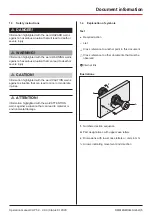
background image

OperatiOn manual

Combined heat and power unit neoTower

®


CHP 5.0 - 30.0

Status 01.2020

Summary of Contents for neoTower

Page 1: ...Operation manual Combined heat and power unit neoTower CHP 5 0 30 0 Status 01 2020 ...

Page 2: ...13 5 Assembly 14 5 1 Safety instructions for assembly 14 5 2 Installation location requirements 14 5 2 1 Overview of the installation location 14 5 2 2 Installation room 15 5 2 3 Heating system 16 5 2 4 Flue gas routing 16 5 2 5 Exhaust air duct 16 5 2 6 Supply air supply 16 5 2 7 Gas supply 17 5 2 8 Water supply 17 5 2 9 Condensate drain 17 5 2 10 Power supply 17 5 2 11 Reactive current compensat...

Page 3: ...r connected directly to buffer tank 36 12 2 2 Heating system variant 2 1 CHP 2 buffer tanks peak load boiler connected directly to buffer tank 37 12 2 3 Heating system variant 3 1 CHP 1 buffer tank peak load boiler connected to buffer tank via hydraulic separator 38 12 2 4 Heating system variant 4 1 CHP 2 buffer tanks peak load boiler connected to buffer tank via hydraulic separator 39 12 2 5 Heat...

Page 4: ...ocumentation valid for the delivered system e g technical data maintenance plan is included in the scope of delivery RMB Control operating manual The RMB Control operating manual describes how to control the system via the operational display and is included in the scope of delivery Wiring diagrams The wiring diagrams are located on the inside of the control cabinet door Manuals for system compone...

Page 5: ...hted with the word CAUTION warns against a situation that can lead to minor or moderate injuries D ATTENTION Information highlighted with the word ATTENTION warns against a situation that can lead to material or environmental damage 1 4 Explanation of symbols Text A Required action B List D Cross reference to another point in this document Cross reference to other documents that must be observed Ј...

Page 6: ...duct is installed The operator has the following duties B Fulfilling the requirements specified by the energy provider e g registration approval compensation B Meeting the installation location requirements B Training the user B Complying with statutory occupational health and safety obligations B Complying with the valid safety accident prevention and environmental protection regulations B Provid...

Page 7: ...on B If the supply and return lines e g gas flue gas water electricity condensate drain are altered or modified without authorisation B If any safety devices are missing or inoperable D 3 4 Safety devices page 9 B During the construction phase of the building B If the system has been in storage for more than 5 months after delivery D 4 Storage page 13 B If the system has been decommissioned for mo...

Page 8: ...nto the energy provider s local electricity network in return for compensation A suitable application must be submitted to the energy provider for this purpose 3 3 Modes of operation The system can be operated in five modes of operation including shutdown The modes of operation are set via the operational display RMB Control operating manual 3 3 1 Ready for e car charging button Special mode for c...

Page 9: ...y devices can lead to hazardous situations A Ensure that the protection devices are not removed A Follow the safety instructions on the system A Only remove the covers if you are required and authorised to do so The system is equipped with the following safety devices B Emergency stop switch B Pressure relief valve B Protective covers B Safety stickers 3 5 Product variants B CHP 5 0 B CHP 7 2 B CH...

Page 10: ...ing harness G Supply air intake grille H Housing cover I Expansion tank connection J Type plate K Exhaust air connection room air dependent L Hoop guard 3 6 2 Generation unit CHP 11 0 20 0 The generation unit contains the actual combined heat and power unit with the combustion engine the alternator unit and the heat exchangers The generation unit is the core piece of equipment for producing the el...

Page 11: ...lue gas connection E Condensate connection F Gas connection G Buffer water return line connection H Control cabinet wiring harness I Housing cover J Type plate K Supply air intake grille L Hoop guard 3 6 4 Control cabinet The control cabinet contains all the components required to control the system A F E G B C D B A Housing B Aeration and ventilation C Control cabinet door D Emergency stop switch...

Page 12: ...tic filter MSM filter The combination filter filters magnetite and suspended solids out of the water in the heating system A A B C D E A Valve B Filter head with indication of the direction of flow C Lock nut D Brass cup E Filter cartridge 3 7 Scope of supply A B N D C E F G H I J K L M A Generation unit B Control cabinet C Expansion tank connection block D MSM filter E Valve F Temperature sensor ...

Page 13: ...tor page 6 D ATTENTION Risk of damage caused by improper storage During long periods of downtime lubricants and liquids settle within the system Frost and damp conditions can damage parts of the system A Store the system in a frost free dry place A Arrange for the manufacturer to rust proof the system if it is to be kept out of operation for more than 5 months The shelf life of the preservative is...

Page 14: ...must be transported to the installation location by means of a suitable transportation device e g lift truck If it is not possible to transport it to the installation location e g lack of space A Contact the manufacturer 5 2 Installation location requirements D WARNING Risk of suffocation gas explosions or material damage caused by incorrectly installing the system Failing to observe these require...

Page 15: ...s e g paper paints petrol within the installation location B Use of aggressive substances e g sprays solvents chlorinated cleaning agents paints adhesives in the vicinity of the system If the system is installed in vaulted cellars or bare smooth walled rooms hard walled there is a risk of noise and sound resonance The system must be positioned so that the following requirements are fulfilled B Non...

Page 16: ...act the flue gases via the roof B The dimensions for the exhaust gas ducting and flue must be calculated on an individual basis B The gradient of the horizontal section must be min 5 cm per metre B The flue must be inspected and approved for operation e g by a master chimney sweep B A flue gas silencer must be fitted in the flue gas routing The flue gas silencer optionally available must be instal...

Page 17: ...wing requirements B The condensate drain must be depressurised B The inner diameter of the condensate drain must not be reduced B A neutralization device is recommended for each system to collect condensate containing oil B The siphon must be constructed from a corrosion and acid resistant material e g plastic or stainless steel B The siphon must be regularly filled with water to prevent it from d...

Page 18: ...location requirements page 14 A Ensure that the supply voltage has been and remains disconnected Only connect the supply voltage when instructed in the respective assembly step If accessories e g flue gas silencer exhaust air kit are required for the assembly process A Ensure that the accessory is correctly assembled and ready for connection A Ensure that the lines from the accessories have been l...

Page 19: ... the generation unit in order to move the device into the installation location Disassembly for transport may only be carried out by the manufacturer A Contact the manufacturer A Select a suitable installation location D 5 2 2 Installation room page 15 A Position the balance strips A Place the generation unit on the balance strips A Ensure that the generation unit stands level A Screw on the front...

Page 20: ...ng system it is necessary to follow the appropriate hydraulic diagram D 12 2 Hydraulic diagrams page 35 Always match the connections to the identifiers on the generation unit Pay attention the to connection sizes and type when connecting the lines Generation unit connection sizes Connection Connection size and type CHP 5 0 7 2 CHP 11 0 20 0 CHP 25 0 30 0 Buffer water return line 1 male thread 1 ma...

Page 21: ...can be used if required B The arrow on the filter head points in the direction of flow B Horizontal installation of the filter head B Installation of a valve upstream and downstream from the KMS filter MSM filter manual A Connect the line to the Buffer water return line connection on the generation unit A Connect the line to the MSM filter MSM filter manual Buffer water return line A Connect the l...

Page 22: ...tion unit A Connect the line to the condensate drain Flue gas The line must be laid with a sufficient gradient to the generation unit A Make sure that a suitable flue gas silencer optionally available is present B In the flue gas routing B In close proximity to the generation unit B With horizontal installation with correct discharge of the condensate water A Connect the line to the flue gas conne...

Page 23: ...he line A Ensure that when the exhaust air duct is connected the system is protected against frost and the elements Gas The gas supply must comply with the established regulations e g in Germany TRGI Connection via a gas appliance outlet is not permitted A Connect the line to the gas connection on the generation unit A Connect the line to the connection on the gas supply Cover A Fit the cover ...

Page 24: ...t D 12 2 Hydraulic diagrams page 35 A Guide the cables from the temperature sensors T1 T5 to the control cabinet Observe the associated wiring diagrams for the electrical connection Wiring diagrams 5 3 8 Connecting the modem When connecting the modem the following points must be observed B If the modem is subjected to high temperatures it may not function properly B The length of the connection ca...

Page 25: ...onnection of additional components depends on the heating system D 12 2 Hydraulic diagrams page 35 A Connect any additional components e g peak load boiler equipment of the building control technology to the control mechanism Once all components have been connected A Make sure that the mains connection is de energised A Connect the supply voltage to the control cabinet A Close the control cabinet ...

Page 26: ...ion tank connection block D ATTENTION Risk of material damage to the generation unit If the connection between the expansion tank connection block and the generation unit is interrupted during operation the water supply to the generation unit can burst A Ensure that the expansion tank connection block is correctly connected to the generation unit A Open the valve for the expansion tank connection ...

Page 27: ...e emergency stop switch A Switch on the master switch A Start the test run via the operating display Observe the associated instructions for operation RMB Control operating manual 5 4 5 Checking the system A Check the gas and exhaust gas sealing within the generator unit A Check the gas and exhaust gas sealing of the system A Bleed the cooling system A Remove any leaking cooling medium A Check the...

Page 28: ... leak tight B The control mechanism does not display any error messages B The system has run for a minimum of 15 minutes If the test run has not been successful A Check the assembly steps again up until the connection inspection D 5 3 Assembly steps page 18 A Carry out another test run D 5 4 Test run page 26 If the test run has still not been successful A Contact the manufacturer After the test ru...

Page 29: ...that the system is installed in accordance with the regulations and that the commissioning can be carried out The system must be inspected by the manufacturer or a specialist partner authorised by the manufacturer in accordance with the specifications of the commissioning certificate Once the inspection has been passed the system will be released for permanent operation If the system fails the che...

Page 30: ... the Experts area of the RMB Control control mechanism D 2 2 1 Manufacturer page 6 Only qualified personnel trained by the manufacturer have access to the Specialist area of the RMB Control control mechanism D 2 2 3 Trained personnel page 6 Trained users have access to the non protected areas of the RMB Control control mechanism but not to the Experts and Specialist areas The system must only be o...

Page 31: ...TION Risk of damage caused by cleaning agents Sprays solvents and chlorinated cleaning agents can cause corrosion and changes in properties A Only use suitable cleaning agents At least once a year A Clean the system with a damp cloth In the case of heavier soiling A Clean the system with warm water and a neutral non abrasive cleaning agent domestic washing up liquid pH value 7 If work that creates...

Page 32: ...turer page 6 In the case of specific tasks for maintaining the system A Contact the manufacturer Maintenance manual 9 2 Fault resolution D WARNING Hazard caused by failing to observe the error messages Malfunctions indicate faults with the system or incorrect settings in the control mechanism Malfunctions must be rectified immediately to prevent further subsequent damage A Rectify all faults immed...

Page 33: ...ised during the work The disassembly must only be performed by trained personnel Electrical work must only be performed by qualified skilled electricians D 2 2 3 Trained personnel page 6 A Switch off the system RMB Control operating manual A Close all valves in the system A Close all valves in the heating system A Remove all cables from the control cabinet that are not connected to the generation ...

Page 34: ...om recyclable materials The packaging materials can be put back into to the raw materials cycle after use This will save valuable resources A Separate the packaging according to material and dispose of it in an environmentally friendly manner 11 2 Disposing of the system D ATTENTION Risk of environmental damage caused by failing to dispose of the system in the proper manner A Do not dispose of the...

Page 35: ...iagrams illustrate examples for connecting the system to the heating system These hydraulic diagrams do not replace the need to correctly design the technical aspects heating system The hydraulic diagram applicable to the heating system must be checked for correctness and completeness The installation location requirements must be observed In particular B The building s heating system D 5 2 3 Heat...

Page 36: ... 20 19 21 22 23 T 24 25 T5 1 Shut off 2 Circulating pump 3 Shut off 4 Shut off 5 Combination filter 6 Shut off 7 Drain 8 Safety valve 9 Cap valve 10 Expansion tank 11 Buffer tank 12 Drinking water tank 13 Temperature sensor 14 Ventilation 15 Shut off 16 Shut off 17 Non return valve 18 Circulating pump 19 Shut off 20 Shut off 21 Non return valve 22 3 way mixer 23 Circulating pump 24 Temperature sen...

Page 37: ...T5 1 Shut off 2 Circulating pump 3 Shut off 4 Shut off 5 Combination filter 6 Shut off 7 Drain 8 Safety valve 9 Cap valve 10 Expansion tank 11 Buffer tank 12 Buffer tank 13 Drinking water tank 14 Temperature sensor 15 Shut off 16 Circulating pump 17 Shut off 18 Non return valve 19 Ventilation 20 Shut off 21 3 way mixer 22 Shut off 23 Non return valve 24 Circulating pump 25 Heating circuit consumer...

Page 38: ... 29 30 1 Shut off 2 Circulating pump 3 Shut off 4 Shut off 5 Combination filter 6 Shut off 7 Buffer tank 8 Drinking water tank 9 Circulating pump 10 Temperature sensor 11 Shut off 12 Shut off 13 Non return valve 14 Ventilation 15 Shut off 16 Shut off 17 Non return valve 18 3 way mixer 19 Circulating pump 20 Heating circuit consumers 21 Temperature sensor 22 Ventilation 23 Hydr switches 24 Circulat...

Page 39: ... 1 Shut off 2 Circulating pump 3 Shut off 4 Shut off 5 Combination filter 6 Shut off 7 Drain 8 Safety valve 9 Cap valve 10 Expansion tank 11 Buffer tank 12 Buffer tank 13 Drinking water tank 14 Temperature sensor 15 Shut off 16 Circulating pump 17 Shut off 18 Non return valve 19 Ventilation 20 Shut off 21 3 way mixer 22 Shut off 23 Non return valve 24 Circulating pump 25 Heating circuit consumers ...

Page 40: ...3 Combination filter 4 Circulating pump 5 Shut off 6 Combination filter 7 Drain 8 Safety valve 9 Cap valve 10 Expansion tank 11 Buffer tank 12 Buffer tank 13 Drinking water tank 14 Temperature sensor 15 Shut off 16 Circulating pump 17 Shut off 18 Non return valve 19 Ventilation 20 Shut off 21 3 way mixer 22 Shut off 23 Non return valve 24 Circulating pump 25 Heating circuit consumers 26 Temperatur...

Page 41: ...ower 2 0 50 0 combined heat and power unit complies with all relevant provisions of the following directives Machinery Directive 2006 42 EG Gas Equipment Regulation 2016 426 Low Voltage Directive 2014 35 EU Electromagnetic Compatibility 2014 30 EU VDEW Guidelines for the connection and parallel operation of decentralized power generation systems in the low voltage network DIN VDE 0100 551 Safety o...

Page 42: ...42 RMB ENERGIE GmbH Appendix Operation manual CHP 5 0 30 0 Status 01 2020 12 4 Proof of conformity Generation unit ...

Page 43: ...RMB ENERGIE GmbH 43 Appendix Operation manual CHP 5 0 30 0 Status 01 2020 ...

Page 44: ...any Tel 49 4498 92288 0 Fax 49 4498 92288 66 info rmbenergie com www rmbenergie com Niederlassung Rosenheim Prinzregentenstraße 16 83022 Rosenheim Tel 49 8031 61991 0 Niederlassung Emmelshausen Liesenfelder Straße 79 56281 Emmelshausen Tel 49 6747 95154 0 ...

Reviews: