background image

RT

7

0

Yanmar

® 

4TNV98CT

, equipped with tires or tracks

Operator’s

Manual

CMW®

053-

3307

Issue 

2

.0

Original Instruction

Summary of Contents for RT70

Page 1: ...RT70 Yanmar 4TNV98CT equipped with tires or tracks Operator s Manual CMW 053 3307 Issue 2 0 Original Instruction ...

Page 2: ...ents 4 Regulatory Notices 5 United States 5 Canada 5 Operator Orientation 6 Operating Area 6 About This Manual 7 Bulleted Lists 7 Numbered Lists 7 California Proposition 65 Diesel engine exhaust and some of its constituents are known to the State of California to cause cancer birth defects and other reproductive harm www P65warnings ca gov ...

Page 3: ...umber Location Record serial numbers and date of purchase in spaces provided Serial number is located as shown Item Date of manufacture Date of purchase Machine serial number Front attachment serial number Rear attachment serial number t63om001h21 eps t63om001h21 eps ...

Page 4: ...signed and built in accordance with applicable standards and regulations Modification of equipment could mean that it will no longer meet regulations and may not function properly or in accordance with the operating instructions Modification of equipment should only be made by competent personnel possessing knowledge of applicable standards regulations equipment design functionality requirements a...

Page 5: ...tor s Manual Machine Components Machine Components 1 Rollover Protective Structure ROPS 2 Operator station 3 Center console 4 Engine compartment 5 Backfill blade Optional 1 1 2 2 3 3 4 4 5 5 t63om002h21 eps t63om002h21 eps ...

Page 6: ...arantee that interference will not occur in a particular installation If this equipment does cause harmful interference to radio or television reception which can be determined by turning the equipment off and on the user is encouraged to try to correct the interference by one or more of the following measures Reorient or relocate the receiving antenna Increase the separation between the equipment...

Page 7: ... Orientation Operator Orientation 1 Front 2 Right side 3 Rear 4 Left side Operating Area Operate only from designated seat s IMPORTANT Top view of machine is shown 1 1 2 2 4 4 3 3 t63om003h21 eps t63om003h21 eps t63om004h21 eps t63om004h21 eps ...

Page 8: ...chine Cross references such as See page 50 will direct you to detailed procedures Bulleted Lists Bulleted lists provide helpful or important information or contain procedures that do not have to be performed in a specific order Numbered Lists Numbered lists contain illustration callouts or list steps that must be performed in order ...

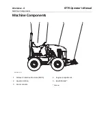
Page 9: ...Overview 8 RT70 Operator s Manual About This Manual ...

Page 10: ...ontact your Ditch Witch dealer If you need assistance in locating a dealer visit our website at www ditchwitch com or write to the following address The Charles Machine Works Inc ATTN Marketing Department PO Box 66 Perry OK 73077 0066 USA The descriptions and specifications in this manual are subject to change without notice The Charles Machine Works Inc reserves the right to improve equipment Som...

Page 11: ... Part number 053 3307 Copyright 2021 by The Charles Machine Works Inc and Ditch Witch are registered trademarks of The Charles Machine Works Inc Other trademarks and trade names are those of their respective owners This product and its use may be covered by one or more patents at http charlesmachine works patents ...

Page 12: ...ety 13 Machine safety alerts and emergency procedures Prepare 31 Procedures for preparing jobsite preparing operator and preparing equipment Controls 39 Machine controls gauges and indicators and how to use them Drive 83 Procedures for startup cold start driving and shutdown Transport 89 Procedures for lifting hauling and retrieving Backhoe 97 Procedures for digging with backhoe Microtrench 103 Pr...

Page 13: ...bsite and rinsing and storing equipment Service 143 Service intervals and instructions for this machine including lubrication replacement of wear items and basic maintenance Specifications 195 Machine specifications including weights measurements power ratings and fluid capacities Support 221 The warranty policy for this machine and procedures for obtaining warranty consideration and training ...

Page 14: ...cation 14 Guidelines 15 Emergency Procedures 16 Electric Strike Description 16 If an Electric Line is Damaged 17 If a Gas Line is Damaged 17 If a Fiber Optic Cable is Damaged 17 If Machine Catches on Fire 17 Machine Safety Alerts 19 For additional precautions see Prepare chapter ...

Page 15: ...els DANGER WARNING and CAUTION Learn what each level means indicates a hazardous situation that if not avoided will result in death or serious injury This signal word is to be limited to the most extreme situations indicates a hazardous situation that if not avoided could result in death or serious injury indicates a hazardous situation that if not avoided could result in minor or moderate injury ...

Page 16: ... safety and emergency procedures and individual responsibilities with all personnel before work begins Safety videos are available from your Ditch Witch dealer or at www ditchwitch com safe Safety Data Sheets SDS are available at www ditchwitch com support Fully inspect equipment before operating Repair or replace any worn or damaged parts Replace missing or damaged safety shields and safety alert...

Page 17: ...lows all paths to ground not just path of least resistance Pipes hoses and cables will conduct electricity back to all equipment Low voltage current can injure or kill Many work related electrocutions result from contact with less than 440 volts Most electric strikes are not noticeable but indications of a strike include power outage smoke explosion popping noises arcing electricity If any of thes...

Page 18: ...d on the situation Immediately shut off engine s if this can be done safely and quickly Remove any ignition source s if this can be done safely and quickly Warn others that a gas line has been cut and that they should leave the area After warning others to leave the area leave jobsite as quickly as possible Immediately call your local emergency phone number and utility company If jobsite is along ...

Page 19: ...Safety 18 RT70 Operator s Manual Emergency Procedures ...

Page 20: ...ation 2 Pre heater Fire or explosion can cause death or serious injury Never use starter fluid 3 Moving machine Fall can cause death or serious injury Only operator is allowed on machine No riders 4 Underground utilities Contact can cause death or serious injury Locate and verify underground utilities before digging or drilling ...

Page 21: ...ty Alerts 5 Misuse of machine can cause death or serious injury Read and understand operator s manual and all other safety instructions before use Know how to use all controls 6 Rollover Crushing can cause death or serious injury Wear seat belt ...

Page 22: ...Attachment Safety Alerts BH70 1 Tiedown location See Transport chapter for more information 2 Moving parts Contact can cause serious injury Stay away 3 Lifted load Crushing can cause death or serious injury Stay away from lifted load and its range of movement ...

Page 23: ...fety Alerts CT70 1 Tiedown location See Transport chapter for more information 2 Moving digging teeth Contact will cause death or serious injury Stay at least 6ft 2m away 3 DANGER stripe decal See Parts Manual for replacement part numbers 6 f t 2 m ...

Page 24: ...cation See Transport chapter for more information 2 Moving parts Contact can cause serious injury Stay away 3 Moving digging teeth Contact will cause death or serious injury Stay at least 6ft 2m away 4 DANGER stripe decal See Parts Manual for replacement part numbers 6 f t 2 m ...

Page 25: ...afety Alerts VP70 1 Tiedown location See Transport chapter for more information 2 Lifted load Crushing can cause death or serious injury Stay away from lifted load and its range of movement 3 Moving parts Contact can cause serious injury Stay away ...

Page 26: ... Safety Alerts MT12 1 Thrown objects Impact can cause injury Wear hard hat and safety glasses 2 Moving digging teeth Contact will cause death or serious injury Stay at least 6ft 1 8m away 3 Moving parts Contact can cause serious injury Stay away ...

Page 27: ...Safety 26 RT70 Operator s Manual Attachment Safety Alerts 4 Tiedown location See Transport chapter for more information 5 Silica dust Exposure can cause lung disease Use breathing protection ...

Page 28: ... Safety Alerts MT16 1 Moving parts Contact can cause serious injury Stay away 2 Thrown objects Impact can cause injury Wear hard hat and safety glasses 3 Moving digging teeth Contact will cause death or serious injury Stay at least 6ft 1 8m away ...

Page 29: ...Safety 28 RT70 Operator s Manual Attachment Safety Alerts 4 Tiedown location See Transport chapter for more information 5 Silica dust Exposure can cause lung disease Use breathing protection ...

Page 30: ...afety Alerts RC20 1 Moving parts Contact can cause serious injury Stay away 2 Tiedown location See Transport chapter for more information 3 Lifted load Crushing can cause death or serious injury Stay away from lifted load and its range of movement ...

Page 31: ...Safety 30 RT70 Operator s Manual Attachment Safety Alerts ...

Page 32: ...ew Job Plan 32 Select Start and End Points 32 Identify Hazards 33 Locate Utilities 33 Classify Jobsite 34 Arrange for Traffic Control 35 Prepare Operator 36 Prepare Equipment 37 Check Supplies 37 Check Equipment 37 Assemble Accessories 38 For additional precautions see Safety chapter ...

Page 33: ...site Consider how slope will affect setup and operation Assess the risks on each slope to determine if factors affecting risks create an unsafe condition for working See Slope Guidelines on page 74 Space Check that starting and ending points allow enough space for working Comfort Consider shade wind fumes and other site features Underground utilities Contact can cause death or serious injury Locat...

Page 34: ... participate in the One Call service In countries that do not have a One Call service contact all local utility companies to have underground utilities located Verify Underground Utilities Have an experienced locating equipment operator sweep area within 20 6 m to each side of proposed excavation to verify previously marked line and cable locations Mark location of all buried utilities and obstruc...

Page 35: ...ful hand digging or soft excavation Have service shut down while work is in progress Have electric company test lines before returning them to service Natural Gas Jobsite Precautions Position equipment upwind from gas lines and use one or both of these methods Expose line by careful hand digging or soft excavation Have service shut down while work is in progress Have gas company test lines before ...

Page 36: ...s You may need to use different methods to safely avoid other underground hazards Talk with those knowledgeable about hazards present at each site to determine which precautions should be taken or if job should be attempted Clear objects such as landscaping fabric cable and wire from the work area These objects may be underground or partially buried Arrange for Traffic Control Vehicle and pedestri...

Page 37: ...at www ditchwitch com safe Safety Data Sheets SDS are available at www ditchwitch com support Use equipment carefully Stop operation and investigate anything that does not look or feel right Jobsite hazards Exposure can cause death or serious injury Use correct equipment and work methods Use and maintain appropriate safety equipment To help avoid injury Wear personal protective equipment including...

Page 38: ... and equipment Check Equipment Fluid Levels fuel engine oil hydraulic fluid engine coolant Condition and Function all controls battery hoses and valves pumps and motors tires or tracks signs guards and shields filters air oil hydraulic belts Improper control function Use can cause death or serious injury If control does not work as described in instructions stop machine and have it serviced ...

Page 39: ...ulatory requirements Counterweights Install counterweights as needed for attachment See Counterweights on page 125 NOTICE Do not drill into ROPS to mount extinguisher Tipover Crushing can cause death or serious injury Follow procedure in operator s manual Drive cautiously To help avoid injury Use attachments or counterweights to make front and rear loads balance when all attachments are raised Con...

Page 40: ...41 Console Center 45 Console Left 48 Console Right 52 Display 59 Gauges and Indicators 59 Soft Keys 64 Main Menu 65 Display Pop Up Messages 67 Display Trench Depth Meter 68 Trench Indicators 68 Soft Keys 69 Depth Meter Screen 70 Soft Keys 73 Microtrencher 75 Plow 77 Seat 78 Standard 78 Suspension 80 ...

Page 41: ... switch To connect move right To disconnect move left NOTICE Do not disconnect with engine running To avoid equipment damage wait two minutes after turning engine off before disconnecting battery To lock out battery disconnect switch insert padlock through hole above handle t63om006h21 eps t63om006h21 eps c00ic654w eps ...

Page 42: ... switch 5 Stow lock control 6 Boom Swing control 7 Remote throttle control 8 Remote start switch 9 Bucket Dipper control 10 Remote engine stop button 11 Swing lock 12 Right stabilizer control 13 Remote ground drive control If equipped Item Description IMPORTANT 1 Seat lock pin To change seat position lift To secure seat position lower 1 1 2 2 4 4 6 6 7 7 8 8 5 5 9 9 10 10 11 11 12 12 3 3 13 13 t63...

Page 43: ...ft 5 Stow lock control To lock push down and into hook To release pull up and into hook NOTICE Always use stow lock during transport 6 Boom Swing control To swing left move left To swing right move right To raise pull To lower push NOTICE Do not operate with backhoe in the stowed upright position Control can perform more than one action at a time By feathering the control operator can combine back...

Page 44: ...otely 9 Bucket Dipper control To open bucket move right To close move left To move dipper in pull back To move out push forward Control can perform more than one action at a time By feathering the control operator can combine backhoe operations 10 Remote engine stop button To stop engine press To shut off machine normally use ignition switch Ignition will not start if remote engine stop is engaged...

Page 45: ...control To lower press right To raise press left 13 Remote ground drive control To move forward press top To move in reverse press bottom NOTICE This control is disabled if tractor seat is occupied Gearbox must be in low and ground drive direction control must be in neutral for remote ground drive to function Ensure that backfill blade if equipped and stabilizers are raised and parking brake is re...

Page 46: ...sole Center 1 Ground drive direction speed control 2 Auxiliary outlet 3 USB 4 Work light switch 5 Hazard light switch 6 Front work light switch 7 Blank 8 Ground drive foot control If equipped 1 1 8 8 3 3 4 4 5 5 6 6 7 7 2 2 t63om008h21 eps t63om008h21 eps ...

Page 47: ... rotate knob to appropriate position Must be in forward or reverse position for ground drive foot control to function See Ground drive foot control on page 47 Display indicates forward neutral or reverse selection Screen icon displays High Medium or Low selection 2 Auxiliary outlet Provides power for other equipment DC12V 10A 120W 3 USB Provides power for mobile devices DC5V 1A 5W DC5V 2 1A 10 5W ...

Page 48: ...ff press bottom 7 Blank 8 Ground drive foot control To move machine press To increase speed press To reduce speed release pedal slightly To function ground drive direction control must be in forward or reverse See Ground drive direction speed control on page 46 Pedal should automatically return to neutral when released Item Description IMPORTANT c00ic600w eps c00ic601w eps ...

Page 49: ...ift control 3 Dig Drive 4 Axle lock switch 5 Parking brake switch 6 Throttle 7 Saw Trench slide control switch 8 Cruise control speed dial 9 Cruise control selector switch 10 Attachment speed direction control 11 Blank If equipped 1 1 2 2 3 3 4 4 5 5 6 6 7 7 8 8 9 9 10 10 11 11 t63om009h21 eps t63om009h21 eps ...

Page 50: ...right 2 Reel carrier lift control To lower press left To raise press right 3 Dig Drive To select dig press left To select drive press right 4 Axle lock switch To set axle lock press left To release press right NOTICE To set axle lock operator must be in seat and ground drive direction control must be in neutral After releasing axle lock drive tractor in reverse 6 2m to fully disengage c00ic642w ep...

Page 51: ...ase pull back 7 Saw Trencher slide control switch To slide saw right move forward To slide left pull back To slide trencher right move forward To slide left pull back 8 Cruise control speed dial To increase engine load while using cruise control turn right To decrease turn left Item Description IMPORTANT c00ic147w eps c00ic160w eps c00ic155w eps c00ic138w eps C ...

Page 52: ...ress right Turn on cruise control only when ground drive motor control is in low ground drive is in neutral 10 Attachment speed direction control To go faster in either direction move farther from neutral NOTICE Control does not automatically return to neutral Item Description IMPORTANT c00ic139w eps C c00ic158w eps ...

Page 53: ...T blade raise lower 9 AST switch Trench cleaner lift control 10 Rear steer adjustment switch 11 Engine shutdown override 12 Rear steer switch Super rear steer switch 13 Microtrencher blade tilt level 14 Ground drive speed hand control 15 Super rear steer mode select 16 Backfill blade Reel winder control 17 Display If equipped 1 1 2 2 3 3 4 4 5 5 6 6 7 7 8 8 9 9 10 10 11 11 12 12 13 13 14 14 16 16 ...

Page 54: ...NOTICE If soil conditions allow operate in float position Lower plow into ground before moving control to float position Do not raise plow with control in float position 4 Plow swing control To swing right push forward To swing left move back To float push switch all the way forward until it latches NOTICE If soil conditions allow operate in float position Lower plow into ground before moving cont...

Page 55: ...iles for optional Depth Meter For use only by qualified Ditch Witch technicians 7 Saw lift Trencher lift control To lower push forward To raise move back 8 Saw stabilizer control MT blade To lower press top To raise press bottom Item Description IMPORTANT c00ic250w eps c00ic209h eps c00ic153w eps ...

Page 56: ...indicate when to press ATS switch 10 Rear steer switch Super rear steer switch Rear steer switch To turn on rear steer press left To turn off rear steer return to center position To center tracks press right Super rear steer switch To engage auto rear steer press left To center tracks return to center To select manual rear steer press right Item Description IMPORTANT AST c00ic797h eps c00ic146w ep...

Page 57: ...12 Rear steer adjustment switch To move rear tracks left press and hold left To move right tracks right press and hold right NOTICE Visually verify track position 13 Microtrencher blade tilt level To tilt blade left press and hold left To tilt blade right press and hold right 14 Ground drive speed hand control To go faster in either direction move farther from neutral This control is disabled in h...

Page 58: ... right side down move right To tilt left side down move left To angle blade to the right twist right To angle blade to the left twist left To float move forward to end press button and release handle To remove from float move back Reel winder mode To spool product off push To spool product on pull To move wheel toward spool move right To move wheel away from spool move left Display indicates float...

Page 59: ...Controls 58 RT70 Operator s Manual Console Right 17 Display Displays graphic symbols for indicators and conditions See Display on page 59 Item Description IMPORTANT w 2 ...

Page 60: ...ion gauge 10 Rear steer status indicator 11 Rear steer direction gauge 12 Backfill blade float indicator 13 Cold start wait indicator 14 Operator presence indicator 15 Parking brake indicator 16 Axle lock indicator Item Description IMPORTANT 1 Engine speed gauge Displays numeric value for engine speed 2 5 10 X100 RPM 1938 15 20 25 30 1500 1750 10 10 78 43 AUTO 78 R P M R P M 000 00 0 F v 60 AST H ...

Page 61: ...umeric value of attachment drive percentage Indicates Plow Indicates Rock Saw Indicates Trencher Indicates Micro trencher AST indicates Anti Stall Technology is active Anti Stall Technology AST icon color indicates status White AST option enabled Green AST is enabled and cruise control is active Yellow AST is active Red AST unsuccessful Attachment and ground drive will shut off To re engage the at...

Page 62: ...oat indicator Lights when backfill blade is in float 13 Cold start wait indicator Lights when cold start aids are active Wait until light turns off before starting engine 14 Operator presence indicator Lights when operator is in seat Part of the start interlock system 15 Parking brake indicator Lights when parking brake is set 16 Axle lock indicator Lights when axle lock is set Item Description IM...

Page 63: ...aust temperature indicator 9 Exhaust cleaning disabled indicator 10 Exhaust cleaning indicator Item Description IMPORTANT 1 Fuel gauge Displays fuel level See Approved Fuel on page 149 2 Engine caution stop indicator Lights yellow when engine needs attention Lights red when operator needs to stop engine 15 5 10 X100 RPM 1938 20 25 30 1500 1750 78 43 AUTO 78 R P M R P M 000 00 0 F v 60 2 10 10 AST ...

Page 64: ...sure is too low 6 Engine coolant temperature gauge Displays engine coolant temperature 7 Voltmeter Displays machine voltage 8 High exhaust temperature indicator Lights when exhaust temperatures are high May light when exhaust cleaning is occurring 9 Exhaust cleaning disabled indicator Lights when operator has disabled exhaust cleaning See Exhaust Cleaning on page 67 10 Exhaust cleaning indicator L...

Page 65: ...RTANT 1 Hide Recall diagnostics key To hide diagnostic message press twice To recall press once 2 Main menu key To select main menu press 2 5 10 X100 RPM 1938 15 20 25 30 1500 1750 10 10 78 43 AUTO 78 R P M R P M 000 00 0 F v 60 AST 1 1 2 2 2 t63om092h21 eps t63om092h21 eps H ...

Page 66: ...iption IMPORTANT 1 Anti Stall Technology AST key To toggle AST press 2 User settings key To customize settings press Display brightness clock settings units of measure and language can be adjusted in this screen 3 Attachment configuration key To access attachment configuration screen press Front and rear attachment configurations can be set in this screen 4 Return key To return to main screen pres...

Page 67: ...aning menu key To display exhaust cleaning information press Parked cleanings can be initiated and automatic exhaust cleanings can be enabled disabled in this screen 8 Diagnostics key To display engine and controller diagnostic codes press For use only by qualified Ditch Witch technicians If diagnostic codes are displayed contact your Ditch Witch dealer Item Description IMPORTANT ...

Page 68: ...ing is needed When pop up message appears 1 Ensure machine is away from combustible material 2 Set parking brake 3 Set engine at low throttle 4 Ensure that engine temperature has reached at least 140 F 60 C 5 Follow on screen prompts to initiate exhaust cleaning After exhaust cleaning is initiated another pop up message will be displayed with the estimated time remaining until process is complete ...

Page 69: ...rench Indicators Item Description IMPORTANT 1 Depth indicator Displays current trench depth 2 Trench rate indicator Displays current trench speed 15 2 5 10 X100 RPM 1938 20 25 30 1500 1750 43 AUTO 78 R P M R P M 000 00 0 F v 000 000 fPM 10 17 78 DM 1 1 2 2 2 t63om098h21 eps t63om098h21 eps H ...

Page 70: ...m Description IMPORTANT 1 Depth meter screen key To enter depth meter screen press 2 Main menu key To return to main menu press 15 2 5 10 X100 RPM 1938 20 25 30 1500 1750 43 AUTO 78 R P M R P M 000 00 0 F v 000 000 fPM 10 17 78 DM DM 1 1 2 2 2 t63om099h21 eps t63om099h21 eps H ...

Page 71: ...aust cleaning indicator 14 Exhaust cleaning disable indicator 15 Fuel gauge 16 Depth graph line 17 Surface grade graph line 18 Distance trenched graph axis 19 Real time clock 20 Surface grade graph axis Item Description IMPORTANT 1 Current speed gauge Displays current speed 2 Five minute average speed gauge Displays average trench speed from last five minutes 1 1 7 7 2 2 3 3 4 4 5 5 6 6 8 8 9 9 10...

Page 72: ...draulic fluid filter indicator Lights when hydraulic filter is restricted During cold weather light will stay on until hydraulic fluid reaches operating temperature 11 Hydraulic fluid temperature indicator Lights when hydraulic fluid temperature is too high 12 High exhaust temperature indicator Lights when exhaust temperatures are high May light when exhaust cleaning is occurring 13 Exhaust cleani...

Page 73: ...isplays trench depth changes 17 Surface grade graph line Displays surface grade changes 18 Distance trenched graph axis Displays reference for distance trenched 19 Real time clock Displays time 20 Surface grade graph axis Displays reference for surface grade Item Description IMPORTANT ...

Page 74: ...ay toward beginning of job press 2 Manual scroll forward To scroll display toward end of job press 3 Delete stored jobs To delete stored jobs press 4 Export jobs to USB To export stored jobs to USB press For use only by qualified Ditch Witch technicians 5 Exit depth meter screen To exit depth meter screen press 06 57 0 0 3000 1003 RPM 226 F Ft min Ft 80 In 0 0 35 5 35 4 55 0 5 0ft 5ft 10ft 15ft 20...

Page 75: ...Controls 74 RT70 Operator s Manual Display Trench Depth Meter 6 Pause Resume current job To pause current job press To resume press 7 Start new job To start new job press Item Description IMPORTANT ...

Page 76: ...ription IMPORTANT 1 Swing lock handle To lock move handle toward tractor To unlock move handle toward microtrencher In most situations operate with microtrencher locked 2 Manual tilt adjustment To adjust left turn clockwise To adjust right turn counterclockwise Use with bubble level together to adjust microtrencher to match jobsite conditions See Adjust Tilt on page 107 ...

Page 77: ...right microtrencher angle Use with manual tilt adjustment to adjust microtrencher to match jobsite conditions See Adjust Tilt on page 107 4 Level indicator Indicates base of microtrencher is level with pavement Adjust microtrencher base until it is flat on pavement Item Description IMPORTANT ...

Page 78: ...MPORTANT Stow lock control To lock 1 Raise plow fully 2 Move control right 3 Lower plow slightly to engage lock To release 1 Raise plow slightly 2 Push stow lock handle to release lock Use this control to lock plow in the raised position t63om016h21 eps t63om016h21 eps c00ic643w eps ...

Page 79: ... belt is low and tight To release lift top of buckle 2 Pivot control To pivot seat push lever in direction of arrow and rotate seat to desired position To lock seat in place release Seat pivots to the right at 0 5 60 and 90 and to the left at 30 Drive tractor with operator s seat facing front If desired operate rear attachments with seat pivoted 1 1 2 2 3 3 t63om017h21 eps t63om017h21 eps ...

Page 80: ...RT70 Operator s Manual Controls 79 Seat 3 Slide control To slide seat forward or backward pull then adjust seat To lock seat in place release Item Description IMPORTANT ...

Page 81: ...il seat belt is low and tight To release lift top of buckle 2 Pivot control To pivot seat push lever in direction of arrow and rotate seat to desired position To lock seat in place release Seat pivots to the right at 0 5 60 and 90 and to the left at 30 Drive tractor with operator s seat facing front If desired operate rear attachments with seat pivoted 1 1 2 2 3 3 4 4 t63om018h21 eps t63om018h21 e...

Page 82: ...ntrols 81 Seat 3 Suspension control Adjust dial to approximate body weight for additional comfort 4 Slide control To slide seat forward or backward pull then adjust seat To lock seat in place release Item Description IMPORTANT ...

Page 83: ...Controls 82 RT70 Operator s Manual Seat ...

Page 84: ...Drive Chapter Contents Start 84 Operate 85 Slope Guidelines 86 Reduce Track Wear 87 Shut Down 87 For additional precautions see Safety and Prepare chapters IMPORTANT For more information on how to operate controls see Controls chapter ...

Page 85: ...at low throttle until controls operate as described in controls chapter EMERGENCY SHUTDOWN Turn ignition switch off Misuse of machine can cause death or serious injury Read and understand operator s manual and all other safety instructions before use Know how to use all controls To help avoid injury Allow hydraulic fluid time to warm before operating in cold weather Cold hydraulic fluid can length...

Page 86: ... if using the ground drive speed hand control the ground drive foot control will only increase speed any opposing signal from controls causes ground drive to stop When operating in high ground drive stops if ground drive speed hand control is moved out of neutral position NOTICE Drive carefully in congested areas Know machine s clearance and turning radius Survey field of vision when operating mac...

Page 87: ...e and braking performance are two absolute limits which must never be exceeded These maximums are stated below since they are design limits These design limits usually exceed the operating limits and must never be used alone to establish safe operating angle for variable conditions Maximum engine lubrication angle 30 Maximum service brake retarding force equal to traction of all four quad tracks M...

Page 88: ...ack edges pressed against hard walls or curbs operating on corrosive materials such as salt or fertilizer Shut Down 1 When job is complete move machine to level ground 2 Stop machine movement 3 Set parking brake 4 Lower all unstowed attachments to ground 5 Return all controls to neutral 6 Run engine at low throttle with no load for at least three minutes to cool 7 Shut off machine 8 If leaving mac...

Page 89: ...Drive 88 RT70 Operator s Manual Shut Down ...

Page 90: ...ansport Chapter Contents Lift 90 Haul 90 Inspect Trailer 90 Load 91 Tie Down 92 Unload 94 Retrieve 95 For additional precautions see Safety and Prepare chapters IMPORTANT For more information on how to operate controls see Controls chapter ...

Page 91: ...ed to come on with tow vehicle brakes Check trailer bed for cracks Lifted load Crushing weight can cause death or serious injury Stay away from lifted load and its range of movement Misuse of machine can cause death or serious injury Read and understand operator s manual and all other safety instructions before use Know how to use all controls To help avoid injury Read trailer operator s manual be...

Page 92: ...ow engine to low throttle and slowly drive tractor to rear of trailer and align with ramps 7 Drive forward slowly to move machine onto trailer until tiedown position is reached 8 Lower attachments to trailer bed 9 Set parking brake 10 Ensure all controls are in neutral position 11 Shut off machine 12 Tie down machine Horizontal movement Crushing can cause death or serious injury Read and understan...

Page 93: ...e tiedowns are tight before transporting Centerline Trencher Lower trencher to trailer bed and chain at attachment frame and through boom Ensure chains are tight before transporting IMPORTANT If trencher is equipped with a trench cleaner ensure that trench cleaner shoe is fully raised and extra bolt found in operator s manual compartment is installed in appropriate hole for additional support t63o...

Page 94: ...in at attachment frame and vibrator box Ensure chains are tight before transporting IMPORTANT If trencher is equipped with a trench cleaner ensure that trench cleaner shoe is fully raised and extra bolt found in operator s manual compartment is installed in appropriate hole for additional support NOTICE Engage attachment stow lock and swing lock devices in addition to securing at tiedowns t63om021...

Page 95: ... 4 Start engine 5 Release parking brake 6 Raise attachments clear of trailer but keep them low Ensure they are not in float 7 Slow engine to low throttle and slowly back machine down trailer or ramps Horizontal movement Crushing can cause death or serious injury Read and understand operator s manual and all safety instructions before use ...

Page 96: ... points facing towing vehicle 4 Locate four plugs shown on pump housing Thoroughly clean area around plugs 5 Stop engine 6 Remove front two plugs Some fluid will escape 7 Remove relief check valves Set aside 8 Install plugs and tighten until snug 9 Remove blocks 10 Fasten and adjust seat belt 11 Start engine and set throttle to low idle 12 Release parking brake and stop engine 13 After towing rese...

Page 97: ...Transport 96 RT70 Operator s Manual Haul ...

Page 98: ...hapter Contents Set Up 98 Position Tractor 98 Prepare Backhoe 99 Operate 99 Move Machine 99 Finish Job 101 For additional precautions see Safety and Prepare chapters IMPORTANT For more information on how to operate controls see Controls chapter ...

Page 99: ...ent to 6 150mm above ground 7 Lower backfill blade if equipped 8 Adjust throttle to low speed 9 Rotate backhoe operator seat to operation position as shown 10 Move to backhoe operator s station NOTICE Backhoe may obstruct the forward visibility of the operator Machines with limited forward visibility should be driven only with the help of a spotter IMPORTANT Operator must be in backhoe seat to use...

Page 100: ...lade if equipped 4 Adjust throttle to desired speed 5 Dig hole or trench Keep dipper and boom at right angles as much as possible for maximum power Keep bucket in line with dipper as much as possible Position bucket so teeth cut soil As soil is cut curl bucket under dipper Move dipper and bucket together Increasing engine speed will not increase backhoe force 2 2 1 1 t63om026h21 eps t63om026h21 ep...

Page 101: ... ground 2 Raise backfill blade if equipped 3 Move machine 4 Lower stabilizers NOTICE Only use this method to move machine less than 30 10m at one time IMPORTANT Ensure ground drive direction control is in neutral Ensure attachment speed direction control is in neutral Ensure range select is in low ...

Page 102: ... move dipper fully toward boom shown 5 Engage swing lock 6 Rotate seat into stowed position 7 Return to tractor seat and drive a short distance away from work site 8 Shut off machine IMPORTANT For tractor to function once operator has returned to operator station stabilizers must be raised remote throttle must be disabled remote stop must be disengaged and boom must be stowed and locked ...

Page 103: ...Backhoe 102 RT70 Operator s Manual Finish Job ...

Page 104: ...earance 105 Adjust Trench Depth 106 Adjust Tilt 107 Adjust Level Indicator 107 Prepare Spoils Removal 108 Operate 109 Use Trench Cleaner 111 Finish Job 112 For additional precautions see Safety and Prepare chapters IMPORTANT For more information on how to operate controls see Controls chapter ...

Page 105: ...e with planned trench 6 Lower backfill blade 7 Set parking brake 8 MT12 Adjust spoils deflector See Spoils Deflector on page 106 9 MT12 Lower microtrencher to just above ground and adjust tilt See Adjust Tilt on page 107 MT16 Lower microtrencher base to ground 10 Ensure blade is in line with planned trench and that tires are pointing straight ahead 11 MT12 Adjust level indicator 12 Prepare spoils ...

Page 106: ... bits hit frame repeat steps 2 5 to ensure bits are in the proper location and secured at proper depth If bits do not hit frame 1 Install blade cover 2 Fasten and adjust seat belt 3 Start engine 4 Adjust throttle 5 Raise microtrencher slightly 6 Rotate blade slowly and listen for clicking sounds If clicking sound is present turn off tractor and repeat steps 1 6 IMPORTANT If new bits and deflectors...

Page 107: ...or MT12 only 1 Remove blade cover 2 Remove hardware that retain the inside spoils deflector shown 3 Position spoils deflector 4 Reassemble IMPORTANT For best spoils removal set the spoils deflector as close to the blade as possible NOTICE Overtightening nuts will distort deflector ...

Page 108: ...3 until desired tilt is achieved 4 Tighten clamp bolts Adjust Level Indicator MT12 only 1 Remove blade 2 Position base of microtrencher flat on pavement 3 Loosen bolts 1 in adjustable link and align moving pointer 2 with fixed pointer 4 Tighten bolts IMPORTANT Microtrenching requires good contact between microtrencher frame and the surface being cut Lift level and tilt microtrencher to match jobsi...

Page 109: ...avator to vacuum hose on tractor 3 Operate vacuum excavator at full speed for best results Full vacuum flow to microtrencher is needed for best spoils removal Without Vacuum Excavator MT12 only 1 Cap vacuum hose on tractor 2 Remove chute plates 1 3 Install spoils chutes 2 Suction Suffocation will cause death Keep hose end away from face IMPORTANT Read vacuum excavator operator s manual for operati...

Page 110: ... help avoid injury Allow 3 1m between digging teeth and obstacle Machine may jerk when digging starts Keep everyone at least 6 1 8m from machine attachments and their range of movement Only operate with blade cover and chutes or chute plates installed IMPORTANT When possible lower microtrencher into softer material and then move into harder or abrasive material For example lower microtrencher into...

Page 111: ...e microtrencher swing lock when cutting curved trenches IMPORTANT Ground drive speed and direction can be controlled with foot pedal or hand control When trenching set ground drive speed with hand control Use foot pedal to temporarily adjust speed if digging conditions change for a short distance If cutting a curved trench smaller than a 40 12 2m radius make a series of straight cuts ...

Page 112: ...stowed position shown 8 Set trench cleaner to desired depth by matching the number of holes below trench cleaner mounting pin to number of holes below blade motor as shown Trench cleaner should be close to but not touching blade 9 Fasten and adjust seat belt 10 Start engine 11 Start blade rotation and slowly lower microtrencher into trench to continue trenching 12 When finished stop trenching and ...

Page 113: ...top machine movement 2 Adjust to low throttle 3 Raise blade 4 When blade is fully raised stop blade rotation 5 Raise microtrencher 6 Drive a short distance away from work site 7 Shut off machine 8 MT12 Wash bits and mounting blocks with high pressure water before parking machine overnight ...

Page 114: ...Set Up 114 Position Tractor 114 Attach Product 114 Prepare Tractor 115 Operate 116 Special Plowing 117 Finish Job 118 For additional precautions see Safety and Prepare chapters IMPORTANT For more information on how to operate controls see Controls chapter ...

Page 115: ...ed plow path 4 Set parking brake 5 Lower backfill blade if equipped 6 If equipped with combo enable plow operation 7 Lower plow to starting point of trench 8 Shut off machine Attach Product Pull Product 1 Insert material into pulling grip as shown 2 Tape grip with duct tape IMPORTANT If material must be at a constant depth dig starting and target trenches ...

Page 116: ... Tractor 1 Fasten and adjust seat belt 2 Start engine 3 Set to low throttle 4 Release parking brake 5 Select low ground drive speed 6 Lower reel carrier if equipped to operating position 7 Raise backfill blade if equipped 8 Turn seat to desired position 9 Engage axle lock IMPORTANT Use only genuine Ditch Witch cable guide NOTICE Use extreme caution when operating reel carrier on sloped surfaces ...

Page 117: ...ease vibration to desired speed 7 Set plow swing to float 8 Set to full throttle 9 Reduce attachment speed to the point with the least tractor vibration and the highest ground drive speed possible without track slippage Adjust vibrator speed if ROPS vibrates excessively 10 Monitor product for damage during plowing NOTICE Do not operate vibrator unless plow is in the ground Do not drive in reverse ...

Page 118: ...or frame Coordinated Plowing Coordinated plowing can be used to turn a tight circle around a jobsite obstacle or in similar conditions 1 Engage rear steer 2 Position the tracks as shown above 2 3 Slowly move tractor forward 4 Plow as normal Crab Plowing Crab plowing can be used to plow along the edge of jobsite or in similar conditions 1 Engage rear steer 2 Position the tracks as shown above 3 3 S...

Page 119: ... Set parking brake 7 Lower backfill blade if equipped 8 Shut off machine 9 Remove product from plow 10 Fasten and adjust seat belt 11 Start machine 12 Swing plow to center position and engage stow lock 13 Release parking brake 14 Raise backfill blade if equipped 15 Disengage axle lock After disengaging axle lock drive tractor in reverse 6 2m to fully disengage 16 Drive a short distance away from w...

Page 120: ...l Carrier Chapter Contents Set Up 120 Adjust Reel Winder 120 Prepare to Plow 120 Operate 120 Finish Job 121 For additional precautions see Safety and Prepare chapters IMPORTANT For more information on how to operate controls see Controls chapter ...

Page 121: ...is on 5 Lower backfill blade if equipped Operate 1 Lower plow 2 Shut off engine 3 Attach service line to reel 4 Fasten and adjust seat belt 5 Start engine 6 Enable reel winder operation 7 Lower reel winder arm until track meets reel flange 8 Wind service line NOTICE Large reels of conduit or cable may obstruct the forward visibility of the operator Machines with limited forward visibility should b...

Page 122: ...1 Finish Job Finish Job 1 When finished winding raise reel winder arm 2 Set to low throttle 3 Enable backfill blade controls 4 Raise backfill blade if equipped 5 Release parking brake 6 Follow directions in Plow on page 101 to begin plowing ...

Page 123: ...Reel Carrier 122 RT70 Operator s Manual Finish Job ...

Page 124: ...Manual Trench 123 Trench Chapter Contents Set Up 124 Operate 125 Finish Job 127 For additional precautions see Safety and Prepare chapters IMPORTANT For more information on how to operate controls see Controls chapter ...

Page 125: ...t above ground 8 Check that attachment speed direction and ground drive controls are in neutral 9 Lower backfill blade if equipped to reduce shock when trenching begins IMPORTANT When cutting asphalt start trench in soil at edge of road and use shortest possible boom at full depth Sight along center of hood to a stake driven beyond end of trench line for straight trench For optimal spoils delivery...

Page 126: ...ep everyone at least 6 1 8m from machine attachments and their range of movement Know soil conditions and adjust digging speed accordingly Moving digging teeth Contact will cause death or serious injury Stay at least 6 1 8m away To help avoid injury Allow 3 0 91m between digging teeth and obstacle Machine may jerk when digging starts Keep everyone at least 6 1 8m from machine attachments and their...

Page 127: ... back up with trench cleaner in working position IMPORTANT Ground drive speed direction can be controlled with foot pedal or hand control When trenching set ground drive speed with hand control Use foot pedal to temporarily adjust speed if digging conditions change for a short distance Always start trenching with ground drive speed set to low Increase ground drive speed only as soil conditions per...

Page 128: ...vement 2 Set to low throttle 3 Raise boom 4 As boom clears top of trench stop chain movement 5 If equipped with traversing trencher return trencher to center position 6 Raise trench cleaner if equipped 7 Drive a short distance away from work site 8 Shut off machine 9 Stow trench cleaner if equipped ...

Page 129: ...Trench 128 RT70 Operator s Manual Finish Job ...

Page 130: ...ents Chain Teeth and Sprockets 130 Chain and Tooth Maintenance 130 Chain Type 130 Chain Selection 131 Cruise Control 132 Optional Equipment 135 Tractor 135 Backhoe 135 Microtrencher 136 Plow 137 Trencher 137 Counterweights 138 For additional precautions see Safety and Prepare chapters ...

Page 131: ...o premature wear and failure Maintain proper amount of tension on digging chain Overtightening will cause chain stretch and loss of machine performance For correct tightening procedure see Maintenance on page 143 Use tooth pattern most appropriate for digging conditions If conditions change contact your Ditch Witch dealer for information about the most effective chain type and tooth pattern Chain ...

Page 132: ...ended Soil Description Sandy soil Sugar sand blow sand or other soils where sand is the predominant component Soft soil Sandy loam Medium soil Loams loamy clays Hard soil Packed clays gumbo all compacted soils Rocky soil Chunk rock glacial till cobble rip rap gravel Sticky soil Gumbo sticky clays Chain Sandy Soil Soft Soil Medium Soil Hard Soil Rocky Soil Sticky Soil 2 pitch cup tooth 2 3 1 1 3 4 ...

Page 133: ...o high throttle 8 Slowly drive forward 9 Slowly adjust cruise control speed dial to match digging conditions 10 When finished microtrenching return controls to neutral 11 Turn cruise control off 12 Allow chain to dig itself free before stopping attachment EMERGENCY SHUTDOWN Turn ignition switch off IMPORTANT See Controls on page 27 IMPORTANT When cruise control is active ground drive system is int...

Page 134: ...ng attachment Anti Stall Technology RT70 tractors equipped with trenchers include Anti Stall Technology AST as part of cruise control AST will detect impending stall conditions and will attempt to prevent engine from stalling during trenching AST can be turned on in the main menu See Main Menu on page 65 1 Ensure that Anti Stall Technology is turned on 2 Ensure ground drive is in neutral 3 Ensure ...

Page 135: ...al AST icon will turn red if process fails or if AST switch is not pressed 12 If AST icon turns red trencher and ground drive will stop Ground drive and trencher must be set to neutral before system will allow operation to continue Operator may have to manually control boom and ground drive to clear chain of obstruction 13 When finished trenching return controls to neutral 14 Turn cruise control o...

Page 136: ...pitation Flasher light kit Mounts to ROPS GPS Allows tracking of position Hydraulic manifold kit Allows hydraulically driven attachments to be connected Lights with front weights Adds light to front weight kit Lights with reel carrier Adds light to reel carrier SMV sign mount Adds mounting point for slow moving vehicle SMV sign Super Rear Steer Allows additional automatic steering modes Tires Trac...

Page 137: ...place as needed to increase efficiency and keep from damaging machine Blades Provides options for cutting trenches 0 75 19mm 0 95 24mm or 1 25 32mm wide Chute kit Allows spoils to be directed Vacuum hose kit Connects vacuum hose on trencher to hose on vacuum excavation machine includes hose guides that mount to side of trencher ...

Page 138: ...eed cable installation Reel carrier Designed to fit Ditch Witch equipment and speed cable installation Reel winder Rotates reel carrier spool Tape dispenser For marking tapes Equipment Description Booms Several boom length options available Long auger extensions For conditions that require spoils to be moved farther from the trench Trench cleaner Hydraulic cleaner removes spoils from the trench fl...

Page 139: ... attachment configurations may require additional tire options See Tire Fill on page 139 CT70 ST70 MT12 MT16 Front Attachment Weight Rack BH70 RC20 Tires Front weight Rear weight Quad Front weight Rear weight Counterweights required Counterweights not required Front Attachment Weight Rack BH70 RC20 Tires Front weight Rear weight Quad Front weight Rear weight Counterweights required Counterweights ...

Page 140: ... weight o o o Counterweights required o Counterweights recommended for performance Counterweights not required Rear Attachment CT70 MT12 MT16 ST70 VP70 Front Attachment Weight Rack Front tires o o Rear tires o o RC20 Front tires Rear tires BH70 Front tires Rear tires Urethane fill Solid tires or urethane fill o Urethane fill recommended for performance Fill not required ...

Page 141: ...Systems and Equipment 140 RT70 Operator s Manual Counterweights ...

Page 142: ...RT70 Operator s Manual Complete the Job 141 Complete the Job Chapter Contents Restore Jobsite 142 Rinse Equipment 142 Stow Tools 142 For additional precautions see Safety and Prepare chapters ...

Page 143: ...ls rather than moving all spoils at once 4 Repeat on other side of trench if needed 5 Engage float and make final pass over trench Rinse Equipment Spray water onto equipment to remove dirt and mud Stow Tools Ensure tools and accessories are loaded and properly secured on trailer or truck NOTICE Never spray water onto operator s console or electrical center in engine compartment Water can damage el...

Page 144: ...emperature Chart 148 Approved Coolant 148 Approved Fuel 149 Tractor Service Interval Chart 150 Tractor Procedures 151 Backhoe Maintenance Interval Chart 169 Backhoe Procedures 169 Microtrencher Maintenance Interval Chart 170 Microtrencher Procedures 170 Plow Maintenance Interval Chart 176 Plow Procedures 177 For additional precautions see Safety and Prepare chapters IMPORTANT For more information ...

Page 145: ...Maintenance 144 RT70 Operator s Manual Trencher Maintenance Interval Chart 183 Trencher Procedures 184 ...

Page 146: ...equipment such as insulated boots and gloves breathing protection and face shield etc available for use depending on jobsite hazards or requirements Misuse of machine can cause death or serious injury Read and understand operator s manual and all other safety instructions before use Know how to use all controls To help avoid injury Unless otherwise instructed all service should be performed with t...

Page 147: ...s or tracks Contact your Ditch Witch dealer to switch between tracks and tires Your dealer will adjust steering stop settings to match whether the machine is on tracks or tires NOTICE Welding can damage electronics Welding currents can damage electronic components Always disconnect the ECU ground connection from the frame harness connections to the ECU and other electronic components prior to weld...

Page 148: ...nt low silicate fully formulated meeting ASTM D6210 See Approved Coolant on page 148 DEO Diesel engine oil meeting or exceeding API service classification CJ 4 ACEA E6 or JASO DH 2 Engine must use low sulfated ash phosphorous and sulfer low SAPs oil See viscosity chart API American Petroleum Institute ACEA European Automobile Manufacturer s Association EPG Extreme pressure grease polyurea based NL...

Page 149: ...055 NOTICE Use only pre diluted coolant or concentrated coolant mixed with distilled water Do not use tap water Using water or high silicate automotive type coolant will lead to engine damage or premature engine failure Mixing heavy duty diesel engine coolant and automotive type coolants will lead to coolant breakdown and engine damage Temperature range anticipated before next oil change 30 20 10 ...

Page 150: ... is needed when using biodiesel especially when operating in cold weather or storing fuel Contact your Ditch Witch dealer or the engine manufacturer for more information Ultra Low Sulfur Diesel ULSD poses a greater static ignition hazard than earlier diesel formulations with higher sulfur content Avoid death or serious injury from fire or explosion consult with your fuel or fuel system supplier to...

Page 151: ...al Lube initial Check Change Lube Service Before Startup 10 Hours 50 Hours 100 Hours 200 Hours 500 Hours 1000 Hours 2000 Hours As Needed Axle spindle pins Axle trunion mounts Battery Belt engine drive Coolant Dust ejector valve Engine compartment Filter air Filter engine oil see Oil engine Filter fuel Filter hydraulic see Fluid hydraulic Fluid hydraulic Hydraulic hoses Oil differential Oil engine ...

Page 152: ...wn with EPG every 250 hours Parking brake Radiator Seat belt Tires Track hub bolts Track pivot bearings Track rollers and sprocket Track tension Universal joints Water separator Service Before Startup 10 Hours 50 Hours 100 Hours 200 Hours 500 Hours 1000 Hours 2000 Hours As Needed t63om027h21 eps t63om027h21 eps ...

Page 153: ...se a single 12V maximum source for charging Never connect to rapid chargers or dual batteries Never lean over battery when making connections Never allow vehicles to touch when charging Never short circuit battery terminals for any reason or strike battery posts or cable terminals Refer to Safety Data Sheet SDS for additional information regarding battery NOTICE Electronic components can be easily...

Page 154: ...sen and remove battery cable clamps carefully negative cable first 4 Clean cable clamps and terminals to remove dull glaze 5 Check for signs of internal corrosion in cables 6 Connect battery cable clamps positive cable first 7 Tighten any loose connections 8 Ensure battery tiedowns are secure 9 Turn battery disconnect if equipped on t63om028h21 eps t63om028h21 eps ...

Page 155: ...egative cable clamp to negative post of battery A in service vehicle 9 Connect the other black negative cable clamp to engine or frame ground on disabled vehicle at least 12 305 mm from failed battery as shown 10 Operate service vehicle engine at 1500 2000 rpm for a few minutes to build an electrical charge in failed battery 11 Stop engine in service vehicle 12 Remove jumper cables from service ve...

Page 156: ...cks and wear If damaged change belt Change 1 Rotate fan idler Shown to relieve belt tension 2 Replace belt 3 Slowly return tensioner to normal operating position NOTICE Spring loaded tensioner maintains tension on belt Periodically check that tensioner arm is not bottomed out against stop or showing signs of wear t63om029h21 eps t63om029h21 eps ...

Page 157: ... level at bottom of fill neck Test Use hydrometer or refractometer to test coolant freeze protection level Recommended freeze protection level is 34 F 37 C If colder temperatures are expected consult your Ditch Witch dealer or coolant supplier Use pre diluted coolant to maintain proper freeze protection Change 1 Remove plug 2 to drain 2 Install plug 3 Add DEAC at fill to keep level visible at sigh...

Page 158: ... Compartment Check casing below fan shown for debris mud water and ice buildup every 10 hours and after long term storage Manually clean out debris as needed NOTICE Check more often if operating in large brush grassy conditions or if machine is being stored Do not use water or compressed air to remove debris t63om031h21 eps t63om031h21 eps t63om032h21 eps t63om032h21 eps ...

Page 159: ...sh cover 5 Insert secondary element if required and ensure it is seated correctly 6 Insert new primary element 7 Reinstall cover 8 Reset air filter service indicator NOTICE Only open the air filter canister when air filter service indicator shows that service is needed Change the elements Do not attempt to clean them Improperly installed primary element can lead to premature engine failure Cleanin...

Page 160: ...RT70 Operator s Manual Maintenance 159 Tractor Procedures Filter Fuel Check filters 1 2 every 10 hours Change every 500 hours 1 1 2 2 t63om034h21 eps t63om034h21 eps ...

Page 161: ...ter changes every 500 hours Check 1 Check level at sight glass 4 2 Add THF at fill 3 as needed to keep level at halfway point on sight glass Change 1 Remove plug 1 to drain 2 Install plug 3 Change filter 2 if necessary 4 Add THF at fill to keep level at halfway point on sight glass NOTICE Change every 500 hours if jobsite temperature 100 F 38 C more than 50 of the time of if jobsite is extremely d...

Page 162: ...ather than hands to check for leaks Before disconnecting a hydraulic line turn engine off and operate all controls to relieve pressure Lower block or support any raised component with a hoist Cover connection with heavy cloth and loosen connector nut slightly to relieve residual pressure Catch all fluid in a container Before using system check that all connections are tight and all lines are undam...

Page 163: ...isible Oil Engine Check every 10 hours Change after 250 hours and every 500 hours thereafter Check 1 While oil is warm check level at dipstick 4 2 Add DEO at fill 2 as needed to keep level at highest line on dipstick Change 1 While oil is warm remove plug on drain 3 to drain 2 Install plug 3 Remove filter 1 and replace with new filter 4 Add DEO at fill to keep level at highest line on dipstick 1 1...

Page 164: ...x Oil Planetary Wheel End Check every 250 hours Change every 1000 hours Check 1 Position wheel with plug at midway position A 2 Remove tire or track 3 Check that level is visible at plug 4 Add MPL at plug as needed to keep level visible at plug Change 1 Position wheel with plug at bottom B 2 Remove tire or track 3 Remove plug to drain oil 4 Reposition wheel with plug at midway position 5 Add MPL a...

Page 165: ...hten bolts on left side Tighten left front bolt 30 Tighten left rear bolt 30 Repeat until brake releases 5 Repeat step 4 on right side Engage 1 Loosen bolts on left side Loosen left front bolt 30 Loosen left rear bolt 30 Repeat until brake engages 2 Repeat step 1 on right side 3 Remove bolts 4 Reinstall bolts with spacers 5 Tighten NOTICE It is not necessary to fully tighten bolts t63om094h21 eps ...

Page 166: ...with compressed air or spray wash 2 Remove plates on right side of machine and spray through radiator toward exterior 3 If grease and oil are present on radiator spray with solvent and allow to soak overnight NOTICE Radiator may need to be cleaned more frequently in dusty or grassy conditions NOTICE Do not damage fins with high pressure air or water t63om040h21 eps t63om040h21 eps ...

Page 167: ...treme or unusual wear Check the area near the buckle and latch and anywhere the seat belt has contact with equipment or seat Retractor Check that the retractor 3 operates smoothly when the belt is pulled and released Retractor should spool belt without locking Mounting Hardware Check the seat belt mounting hardware 4 on both sides of the seat to ensure it is tight Replace missing damaged or corrod...

Page 168: ...urs Tighten to 295ft lb 400N m as needed Track Pivot Bearings Lube at zerk shown with MPG every 50 hours Track Rollers and Sprocket Check rollers and sprocket shown every 100 hours Replace as needed t63om043h21 eps t63om043h21 eps t63om044h21 eps t63om044h21 eps t63om045h21 eps t63om045h21 eps ...

Page 169: ... nut 2 until no red is visible in adjustment window 3 Tighten jamb nuts Universal Joints Lube joints shown at zerks with MPG after 50 hours and every 250 hours thereafter Water Separator Check water separator shown located on fuel filter before startup and every 10 hours Drain water as needed until fuel runs from drain 1 1 2 2 3 3 t63om046h21 eps t63om046h21 eps t63om047h21 eps t63om047h21 eps t63...

Page 170: ...ted service procedures See detailed information below Backhoe Procedures Pins and Bushings Change pins 1 and bushings 2 when worn or damaged Adjust service or test Change initial Lube initial Check Change Lube Service 10 Hours 50 Hours 100 Hours 250 Hours 500 Hours 1000 Hours 2000 Hours As Needed Pins and bushings 1 1 2 2 t63om049h21 eps t63om049h21 eps ...

Page 171: ...icrotrencher Procedures Attachment Mounting Bolts Check bolts shown every 10 hours 1 Check for looseness or wear 2 Apply Loctite 271 3 Tighten to 200ft lb 271N m Adjust service or test Change initial Lube initial Check Change Lube Service 10 Hours 100 30 5m 100 Hours As Needed Attachment mounting bolts Blade and bits Deflectors Level cylinder Slide plate Tilt adjustment Traverse frame Vacuum hose ...

Page 172: ...es every 100ft 30 5m Replace wear bars and hard surface material as needed to protect bit holders Change blade when bits wear bars and hard surface material can no longer be replaced Rotating Conical Bits 1 Check bit condition using gauge shown 301 1507 A Replace bits B Bits OK 2 As needed drive out roll pin 2 3 Remove bit 1 4 Install new bit into holder 5 Drive in new roll pin 1 2 t61om016w19 eps...

Page 173: ... spanner wrench 2 and cover 3 5 Loosen clamp bolts 4 and remove large nut 5 6 Remove spacer 6 and blade 7 7 Clean threads on hub 8 and nut 6 If needed apply dry lubricant such as graphite or silicone to threads 8 Install new blade note direction of rotation spacer and large nut 9 Fully tighten large nut 10 Tighten clamp bolts to 100 120ft lb 135 160N m 11 Loosen clamp bolts and repeat steps 8 and ...

Page 174: ...hine 4 Remove 6 wingnuts 1 from cover 2 5 Remove 6 lug nuts 3 6 Remove blade 4 7 Clean threads 5 8 Install new blade note direction of rotation and secure with 6 lug nuts 9 Tighten lug nuts to 600ft lb 813 5N m 10 Install cover and secure with wingnuts Deflectors MT12 Check deflectors shown every 10 hours when not using a vacuum for spoils removal Clean vacuum chute as needed Change spoils deflect...

Page 175: ...rotrencher to just above the ground 5 Shut off machine 6 Connect jumper hose 2 to test ports on left side of microtrencher 7 Start machine and select low speed 8 Slowly extend level cylinder to full length Hold lever there for 10 seconds to return trapped air to tank 9 Slowly retract level cylinder Hold lever for 10 seconds to return trapped air to tank 10 Repeat steps 8 and 9 11 Shut off machine ...

Page 176: ...70 Operator s Manual Maintenance 175 Microtrencher Procedures Tilt Adjustment MT12 Lube zerks shown with MPG every 100 hours Vacuum Hoses Check hoses shown every 10 hours Clean out caked spoils as needed ...

Page 177: ...rvice procedures See detailed information below Adjust service or test Change initial Lube initial Check Change Lube Service 10 Hours 50 Hours 100 Hours 250 Hours 500 Hours 1000 Hours 2000 Hours As Needed Arm pins and bushings Attachment mounting bolts Connector pivots Feed tube Lift cylinder Oil vibrator Pivots Plow blade bolts Shear mounts Sod cutter and blade ...

Page 178: ...s and Bushings Check pins and bushings shown every 10 hours Tighten as needed Attachment Mounting Bolts Check bolts shown every 10 hours 1 Check for looseness or wear 2 Apply Loctite 271 3 Tighten to 230ft lb 312N m t63om051h21 eps t63om051h21 eps t63om052h21 eps t63om052h21 eps ...

Page 179: ...draulic load on pivot joints Do not raise plow 3 As hydraulic load is applied and released check joints for motion at joints 1 If motion is observed contact your Ditch Witch dealer Lower Arm Joints 1 Lower plow to ground 2 Use hydraulic jack to place load on lower arm 3 As hydraulic load is applied and released check joints 2 for motion If motion is observed contact your Ditch Witch dealer t63om05...

Page 180: ... Maintenance 179 Plow Procedures Feed Tube Clean feed tube shown as needed Lift Cylinder Check pins and bumpers shown for wear every 50 hours Replace as needed t63om055h21 eps t63om055h21 eps t63om056h21 eps t63om056h21 eps ...

Page 181: ...keep level at halfway point on sight glass Change 1 Move plow vibrator to horizontal position 2 Open fill 2 to vent vibrator 3 Remove plug 3 to drain 4 Install plug 5 Add MPL at fill until level is at halfway point on sight glass Hot parts Contact can cause burns Only touch when cool or wear gloves NOTICE Change every 250 hours if jobsite temperature 100 F 38 C more than 50 of the time 1 1 2 2 t63...

Page 182: ...ocedures Pivots Lube pivots shown with EPG every 10 hours Plow Blade Bolts Check bolts shown as needed 1 Check for looseness 2 Apply Loctite 242 blue 3 Tighten bolts to 210ft lb 285N m t63om059h21 eps t63om059h21 eps t63om060h21 eps t63om060h21 eps ...

Page 183: ...unts shown every 100 hours Replace as needed Sod Cutter and Blade Change sod cutter and blade shown as needed IMPORTANT When replacing shear mounts compress the mounts with washers to prevent the mount from tearing t63om061h21 eps t63om061h21 eps t63om063h21 eps t63om063h21 eps ...

Page 184: ...ormation below Adjust service or test Change initial Lube initial Check Change Lube Service 10 Hours 50 Hours 500 Hours 1000 Hours As Needed Attachment mounting bolts Auger bearings Auger bolts Auger shaft Boom mounting bolts Digging chain Digging chain tension Headshaft motor shaft Oil gearbox Personnel restraint bar Trench cleaner bolts Pivot Restraint bar position Tail roller Trench cleaner pos...

Page 185: ...ighten inner bolts 2 to 230ft lb 312N m 4 Tighten outer bolts 1 to 449ft lb 608N m Auger Bearings Lube two bearing zerks one on each side shown with EPG every 10 hours Auger Bolts Check bolts every 10 hours For optimal spoils delivery adjust augers shown to match terrain and digging depth 1 1 2 2 t63om063h21 eps t63om063h21 eps t63om064h21 eps t63om064h21 eps t63om065h21 eps t63om065h21 eps ...

Page 186: ...uger Shaft Lube two auger shaft zerks one on each side shown with EPG every 10 hours Boom Mounting Bolts Check 5 bolts shown every 10 hours 1 Check for looseness or wear 2 Tighten to 250ft lb 339N m t63om066h21 eps t63om066h21 eps t63om067h21 eps t63om067h21 eps ...

Page 187: ...ce between chain pins 3 and comparing it with a new chain Sidebars If sidebars 2 are bent or loose on chain pins chain spacers should be used to join sidebars Teeth Check teeth 1 for wear Contents under pressure Impact can cause death or serious injury Relieve pressure before opening To help avoid injury Service digging boom grease cylinder only while standing on opposite side of boom Cover connec...

Page 188: ...n until connector pin is on top of boom 4 Lower boom to ground 5 Set parking brake 6 Shut off machine 7 Secure chain by clamping links on either side of connector pin with chain jaws as shown Squeeze jaws to reduce pressure on connector pin 8 Loop cable through links nearest connector pin NOTICE Replace sprockets when a new chain is installed ...

Page 189: ...ain tension 10 Stand clear of chain and remove lock key from connector pin 11 Drive connector pin out of link 12 Unclamp links Slowly release cable and lower chain to ground 13 Lay chain on ground with teeth down Raised component Crushing can cause death or serious injury Stay away Use correct equipment and procedures t63om068h21 eps t63om068h21 eps ...

Page 190: ... 10 Shut off machine 11 Pull rear end of chain over and about 10 260mm past tail roller 12 Use hoist to pull front end of chain over headshaft sprocket 13 Move chain down boom until chain connector pin and lock key can be installed 14 Install connector pin and lock key 15 Tighten chain by pumping EPG into grease cylinder Time Augers Ensure augers are balanced as shown If auger timing is off machin...

Page 191: ...be 4 5 5 5 114 140mm 2 To tighten chain lube cylinder 1 with MPG To relieve chain tension loosen plug on grease cylinder Contents under pressure Impact can cause death or serious injury Relieve pressure before opening To help avoid injury Service digging boom grease cylinder only while standing on opposite side of boom Cover connection with heavy cloth when relieving pressure in cylinder 1 1 2 2 t...

Page 192: ...ings 5 Remove and replace motor if bearings are loose enough to allow oil to leak from seal Personnel Restraint Bar Trench Cleaner Bolts Check all bolts securing restraint bar trench cleaner to arm 4 on each side shown and arm to boom every 10 hours Check all bolts securing restraint bar trench cleaner to machine every 10 hours 1 Check for looseness or wear 2 Apply Loctite 271 3 Tighten bolts hold...

Page 193: ...n left side of trencher pivot clean and lube with EPG every 10 hours Restraint Bar Position Check every 10 hours or anytime the digging chain is adjusted or replaced 1 Ensure end of bar extends between the center of the tail roller sprocket and the end of the digging chain 2 Check for looseness or wear t63om071h21 eps t63om071h21 eps t63om091h21 eps t63om091h21 eps t63om072h21 eps t63om072h21 eps ...

Page 194: ...RT70 Operator s Manual Maintenance 193 Trencher Procedures Tail Roller Remove plug shown to access zerk Clean and lube with EPG every 10 hours t63om073h21 eps t63om073h21 eps ...

Page 195: ...dures Trench Cleaner Position Check trench cleaner position if equipped every 10 hours or anytime the digging chain is adjusted or replaced Ensure there is 3 4in 76 102mm between the digging teeth and the inside of the trench cleaner shoe A A t33om90w eps ...

Page 196: ...fications 195 Specifications Chapter Contents RT70 Tractor 196 BH70 Backhoe 205 CT70 Trencher 208 ST70 Trencher 210 VP70 Plow 212 MT12 Microtrencher 214 MT16 Microtrencher 216 RC20 Reel Carrier 218 EU Declaration of Conformity 219 ...

Page 197: ...s 196 RT70 Operator s Manual RT70 Tractor RT70 Tractor L1 L1 L2 L2 L4 L4 L5 L5 W2 W2 W4 W4 H1 H1 A2 A2 t63om074h21 eps t63om074h21 eps L1 L1 L2 L2 L4 L4 L5 L5 W2 W2 W4 W4 H1 H1 A2 A2 t63om075h21 eps t63om075h21 eps ...

Page 198: ...ght solid tires 100 4in 2 55m L1 Nose to rear mount length 101 5in 2 58m L2 Length transport tracks 142 4in 3 62m Length transport 19 0 45 tires 134 8in 3 42m Length transport solid tires 133 5in 3 39m L4 Wheelbase 63in 1 6m L5 Rear axle to attachment mount holes 13 8in 351mm W2 Width tracks 78 5in 1 99m Width 19 0 45 tires 76 8in 1 95m Width solid tires 71 1in 1 81m W4 Tread tracks 60 3in 1 52m T...

Page 199: ... High medium 3 02mph 4 86km h High high 4 22mph 6 79km h 19 0 45 tires Low low 1 21mph 1 95km h Low medium 1 47mph 2 37km h Low high 2 27mph 3 65km h High low 3 53mph 5 68km h High medium 4 29mph 6 9km h High high 6 52mph 10 49km h solid tires Low low 1 15mph 1 85km h Low medium 1 56mph 2 51km h Low high 2 69mph 4 33km h High low 3 55mph 5 71km h High medium 4 55mph 7 32km h High high 6 40mph 10 3...

Page 200: ... 86km h High high 4 22mph 6 79km h 19 0 45 tires Low low 1 23mph 1 98km h Low medium 1 49mph 2 4km h Low high 2 28mph 3 67km h High low 3 55mph 5 71km h High medium 4 29mph 6 9km h High high 5 62mph 9 04km h solid tires Low low 1 15mph 1 85km h Low medium 1 58mph 2 54km h Low high 2 70mph 4 35km h High low 3 37mph 5 42km h High medium 4 57mph 7 24km h High high 5 40mph 8 69km h Operation U S Metri...

Page 201: ...t 10 66m 19 0 45 tires 31 58ft 9 63m solid tires 31 28ft 9 53m Vehicle clearance circle SAE wall to wall with optional backfill blade front and rear steer tracks 24 68ft 7 52m 19 0 45 tires 23 64ft 7 21m solid tires 21 85ft 6 66m Ground clearance tracks 14 94in 379mm 19 0 45 tires 11 15in 283mm solid tires 9 13in 232mm Operation U S Metric ...

Page 202: ...710lb 776kg Front axle trunnion angle level to full tilt 1 2 of full rot 5 2 5 2 Rear axle tilt angle level to full tilt 1 2 of full rot no tilt Track articulation angle 15 15 Front axle steer angle 35 35 Rear axle steer angle 23 23 Backfill Blade U S Metric Blade width 72in 1829mm Blade height 14 9in 378mm Lift height above ground 22 7in 577mm Blade drop below ground 9 4in 239m Maximum swint angl...

Page 203: ...SAE J1995 72 01hp 53 7kW Estimated net power per SAE J1349 62 71hp 46 76kW Rated speed 2500rpm 2500rpm Emissions compliance EPA Tier 4 EU Stage V Power Train Ground drive transmission Two speed transmission with three speed bent axis motor Differentials Planetary steering front and rear with diff loc Service brake Hydrostatic Parking brake SAHR Tires 19 0 45 17 14PR TL Tires with urethane 19 0 45 ...

Page 204: ...110L min Attachment pump forward relief pressure at 2500rpm 5800 6400psi 400 440bar Auxilliary pump capacity 2500 rpm Steering pump 7 2gpm 27 5L min Auxilliary pump 7 2gpm 27 5L min Side of engine BH70 supplementary pump 6 5gpm 24 5L min Auxilliary pump relief pressure 2500 rpm 3000psi 207bar Fluid Capacities U S Metric Fuel tank 25gal 95L Engine oil 11 1qt 10 5L Hydraulic reservoir 18gal 68L Hydr...

Page 205: ...Vibration Levels Plowing Trenching Average vibration transmitted to the operator s hand during normal operation 13 1m sec 4 2m sec Average vibration transmitted to the operator s whole body during normal operation 0 6m sec 0 9m sec Operator seat per ISO 7096 Actual vibration levels depend on the conditions of the operation being performed Noise Level Operator 91 dbA sound pressure per ISO 6394 Ext...

Page 206: ... 4in 975mm Ground clearance 34 6in 879mm D Backhoe length stowed 101 2in 2570mm E Backhoe or basic unit width tracks 78 5in 1994mm Backhoe or basic unit width 19 0 45 76 3in 1938mm F Digging depth max tracks 89 2in 2266mm Digging depth max 19 0 45 tires 93in 2362mm G Digging depth 2ft 0 6m flat bottom tracks 84 7in 2151mm Digging depth 2ft 0 6m flat bottom 19 0 45 tires 88 5in 2248mm E B R U J K P...

Page 207: ...in 3581mm N Swing pivot to centerline axle 46in 1168mm P Bucket rotation 154 154 R Stabilizer spread operating 103in 2616mm U Leveling angle tracks 6 6 Leveling angle 19 0 45 7 7 General U S Metric Bucket Width 12 18in 305 460mm Capacity 1 7 2 6ft 0 05 0 07m Backhoe weight without bucket 2215lb 1005kg Vertical force boom over end and swing arc SAE 48in 1 2m 1685lb 764kg ground level 1685lb 764kg 7...

Page 208: ...s Manual Specifications 207 BH70 Backhoe Vertical forces are for a stationary machine supported by stabilizers Max tool force Using bucket cylinder 4200lb 18 68kN Using arm cylinder 4000lb 17 79kN General U S Metric ...

Page 209: ...res 61in 1549mm B Trench width max 12in 305mm Trench width max 6in 150mm C Boom travel down 61 61 C1 Boom travel up 43 43 E1 Centerline of trench to outside edge left 39 9in 1013mm Centerline of trench to outside edge left 39in 991mm E2 Centerline of trench to outside edge right 38 8in 986mm Centerline of trench to outside edge right 38in 965mm N N N N B B E2 E2 E1 E1 A A F F L L H1 H1 A3 A3 C C C...

Page 210: ...discharge reach from center of trench short auger 18 5in 470mm Soil discharge reach from center of trench long auger 31 6in 803mm Attachment weight without boom chain augers stub and restraint bar 1240lb 562kg Operation U S Metric Headshaft speeds at 2500 engine rpm Ratio low 210rpm 210rpm Ratio standard 235rpm 235rpm Ratio high 290rpm 290rpm Digging chain speeds with 11 tooth 3 110 79mm pitch hea...

Page 211: ... 305mm Trench width min 6in 150mm C Boom travel down 61 61 C1 Boom travel up 43 43 E1 Centerline of trench to outside edge left tracks 15 8 39in 401 991mm Centerline of trench to outside edge left 19 0 45 tires 14 2 38 2in 361 970mm E2 Centerline of trench to outside edge right tracks 15 6 39 6in 142 1501mm Centerline of trench to outside edge right 19 0 45 tires 14 7 38 7in 373 983mm N N N N B B ...

Page 212: ...115 4in 2931mm N Soil discharge reach short auger 18 5in 470mm Soil discharge reach long auger 31 6in 803mm Attachment weight without boom chain augers stub and restraint bar 1730lb 785kg Operation U S Metric Headshaft speeds at 2500 engine rpm Ratio low 210rpm 210rpm Ratio standard 235rpm 235rpm Ratio high 290rpm 290rpm Digging chain speeds with 11 tooth 3 110 79mm pitch headshaft sprocket Ratio ...

Page 213: ...m blade 19 0 45 tires 32 7 32 7 Angle of departure transport 30in 760mm blade tracks 20 3 20 3 Angle of departure transport 30in 760mm blade 19 0 45 tires 27 3 27 3 A3 Angle of departure transport no blade tracks 48 48 Angle of departure transport no blade 19 0 45 tires 42 42 H Angle of depression plow max tracks 7 7 Angle of depression plow max 19 0 45 tires 7 7 A A J J H2 H2 A3 L2 L2 L2 L2 A A H...

Page 214: ... left tracks 39 4in 1001mm Center of plow to outside edge of machine left 19 0 45 tires 38 7in 983mm Center of plow to outside edge of machine right tracks 39 4in 1001mm Center of plow to outside edge of machine right 19 0 45 tires 38 7in 983mm Inclusive blade steer angle 89 89 Plow swing angle 85 85 Suggested maximum Plow blade used will be determined by job requirements and soil conditions Opera...

Page 215: ...learance at wheel 24 4in 620mm L2 Length transport from centerline of real axle 76 4in 1941mm L4 Length transport from front of attachment 64 1in 1628mm T1 Microtrencher offset distance 24in 610mm T2 Centerline of saw to centerline of machine min offset 6 3in 160mm W1 Working width max 74 2in 1885mm W2 Trench width 0 5 1 5in 13 38mm W3 Spoils chute extension same on both sides 8 5in 216mm W4 Cente...

Page 216: ...otrencher tilt adjustment 6 6 Minimum sawing radius will depend on surface conditons and hardness of material being cut Cut will be slightly wider in curved sections of the trench Operation U S Metric Blade speed variable 0 225rpm 0 225rpm Microtrencher motor displacement 29 3in 480cc Vibration Level Average vibration transmitted to the operator s hand during normal operation is 5 2m sec Average v...

Page 217: ...earance at wheel 11 8in 300mm L2 Length transport from centerline of real axle 94 2in 2393mm L4 Length transport from front of attachment 81 4in 2068mm T1 Microtrencher offset distance 24in 610mm T2 Centerline of saw to centerline of machine min offset 6 3in 160mm W1 Working width max 74in 1880mm W2 Trench width 0 5 1 5in 13 38mm W3 Spoils chute extension right sides 16in 406mm W4 Centerline of ma...

Page 218: ...otrencher tilt adjustment 6 6 Minimum sawing radius will depend on surface conditons and hardness of material being cut Cut will be slightly wider in curved sections of the trench Operation U S Metric Blade speed variable 0 139rpm 0 139rpm Microtrencher motor displacement 47 6in 780cc Vibration Level Average vibration transmitted to the operator s hand during normal operation is 5 2m sec Average v...

Page 219: ...L5 Distance from backfill blade to outside edge of reel carrier with max diameter reel 72 5in 1842mm N Reel diameter max 84in 2134mm Attachment weight 649lb 294kg Attachment weight with reel winder 799lb 362kg Capacity 2000lb 907kg Internal width 54in 1372mm N N L5 L5 t63om079h21 eps t63om079h21 eps ...

Page 220: ...X Type Machine Type Engine Power xxx kW Serial Number i DWPXXXXXXXXXXXXXX Conforms to the requirements of 2006 42 EC Machinery Directive 2014 30 EU Electromagnetic Compatibility Directive 2000 14 EC Noise Emission Directive Measured sound power level Annex V XXXdBA Guaranteed sound power level Annex V XXXdBA The Technical Construction File is maintained at the manufacturer s location The manufactu...

Page 221: ...Specifications 220 RT70 Operator s Manual EU Declaration of Conformity ...

Page 222: ... Ditch Witch equipment Always give model serial number and approximate date of your equipment purchase This information should be recorded and placed on file by the owner at the time of purchase Return damaged parts to dealer for inspection and warranty consideration if in warranty time frame Order genuine Ditch Witch replacement or repair parts from your authorized Ditch Witch dealer Use of anoth...

Page 223: ...R PURPOSE AND MERCHANTABILITY IF THE PRODUCTS ARE PURCHASED FOR COMMERCIAL PURPOSES AS DEFINED BY THE UNIFORM COMMERCIAL CODE THEN THERE ARE NO WARRANTIES WHICH EXTEND BEYOND THE FACE HEREOF AND THERE ARE NO IMPLIED WARRANTIES OF ANY KIND WHICH EXTEND TO A COMMERCIAL BUYER ALL OTHER PROVISIONS OF THIS LIMITED WARRANTY APPLY INCLUDING THE DUTIES IMPOSED Ditch Witch products have been tested to deli...

Reviews: