background image

SAIL-

DRIVE

Sail-Drive

OPERATION MANUAL

SD20

SD50

SD50-4T

P/N: 0ASDM-G00101

Summary of Contents for SD20

Page 1: ...SAIL DRIVE Sail Drive OPERATION MANUAL SD20 SD50 SD50 4T P N 0ASDM G00101 ...

Page 2: ...y a product service or maintenance improvement We reserve the right to make any change at any time without notice Yanmar and are registered trademarks of Yanmar Co Ltd in Japan the United States and or other countries All Rights Reserved No part of this publication may be reproduced or used in any form by any means graphic electronic or mechanical including photocopying recording taping or informa...

Page 3: ...rrosion 11 Corrosion Control 11 Shore Power 12 Underwater Drive Coating 13 Before You Operate 15 Propeller Selection 16 Recommended Propeller Size Maximum 16 Fitting a Fixed Propeller 2 Blade 17 Lubricating Oil 18 Filling With Lubricating Oil SD20 SD50 and SD50 4T 19 Checking the Instrument Panel Alarm System 20 Daily Checks 23 Visual Checks 23 Sail Drive Operation 25 Remote Control Device Check 2...

Page 4: ...ear Case 38 Repairing Damaged Coating 38 Inspecting the Anode 38 Inspecting The Folding Propeller 38 Draining Water 38 Periodic Maintenance Procedures 39 After Initial 50 Hours of Operation 39 Every 100 Hours of Operation 48 Every 250 Hours of Operation 49 Every 500 Hours of Operation 49 Every Year 50 Every 2000 Hours of Operation 51 Every 5 Years 51 Specifications 53 System Diagrams 55 Maintenanc...

Page 5: ...1GM10C 2YM15 3YM20 3YM30 3JH4CE 3JH5CE 4JH4ACE 4JH5CE and 4JH4 TCE However instructions for the marine gear box are not necessary as they are included Engines and Sail Drive combinations are available as follows Engine model Sail Drive Model 1GM10C SD20 2YM15 3YM20 3YM30 3JH4CE SD50 3JH5CE 4JH4ACE 4JH5CE 4JH4 TCE SD50 4T SD Operation Manual 1 2009 Yanmar Marine International ...

Page 6: ...This Page Intentionally Left Blank INTRODUCTION 2 SD Operation Manual 2009 Yanmar Marine International ...

Page 7: ...e read and abide by the message that follows the safety alert symbol SAFETY PRECAUTIONS DANGER Indicates a hazardous situation which if not avoided will result in death or serious injury WARNING Indicates a hazardous situation which if not avoided could result in death or serious injury CAUTION Indicates a hazardous situation which if not avoided could result in minor or moderate injury NOTICE Ind...

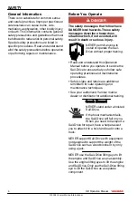
Page 8: ...eration Manual before you operate or service the Sail Drive to ensure that you follow safe operating practices and maintenance procedures Safety signs and labels are additional reminders for safe operating and maintenance techniques See your authorized Yanmar marine dealer or distributor for additional training Crush Hazard NEVER stand under a hoisted Sail Drive If the hoist mechanism fails the Sa...

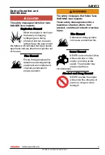
Page 9: ...e installed and checked periodically for proper operation WARNING The safety messages that follow have WARNING level hazards These safety messages describe a hazardous situation which if not avoided could result in death or serious injury Fire Hazard Undersized wiring systems can cause an electrical fire Sever Hazard NEVER service the Sail Drive while under tow or if the engine is running at idle ...

Page 10: ...lock windows vents or other means of ventilation if the engine is operatinginanenclosedarea All internal combustion engines create carbon monoxide gas during operation and special precautions are required to avoid carbon monoxide poisoning CAUTION The safety messages that follow have CAUTION level hazards These safety messages describe a hazardous situation which if not avoided could result in min...

Page 11: ...e or modify the limiting devices such as the engine speed limit fuel injection limit etc Modification will impair the safety and performance of the product and shorten product life Modifications to the design safety or limiting features will void the warranty If the Sail Drive oil temperature is too high stop engine immediately and check the Sail Drive oil level and check the oil cooler for proper...

Page 12: ...This Page Intentionally Left Blank SAFETY 8 SD Operation Manual 2009 Yanmar Marine International ...

Page 13: ... conditions frequently to determine if the maintenance intervals suggested in the manual are frequent enough for your Sail Drive New Sail Drive Break In On the initial engine start up allow the engine to idle for approximately 15 minutes while you check for proper Sail Drive function and Sail Drive oil leaks During the break in period carefully observe Sail Drive seal indicators for proper Sail Dr...

Page 14: ... 1 2 3 4 0006440 5 6 7 Figure 1 1 Dipstick 2 Upper Gear Case 3 Lower Gear Case 4 Lubricating Oil Drain Plug 5 Propeller 6 Seawater Inlet 7 Flexible Mount PRODUCT OVERVIEW 10 SD Operation Manual 2009 Yanmar Marine International ...

Page 15: ...d isolation transformers are also available from the aftermarket not supplied by Yanmar The Galvanic isolator is a device that is installed in series with the AC grounding GREEN conductor of the shore power cable to effectively block low voltage DC galvanic current flow but permit the passage of alternating current AC The rate of corrosion depends on numerous factors such as the number size and lo...

Page 16: ... in marine electricity and corrosion control to determine the best way to correct the rapid erosion of the anodes SHORE POWER Vessels that are connected to shore power require additional protection to prevent destructive low voltage galvanic currents from passing through the shore power groundwire Galvanicisolatorsareavailable from the aftermarket not supplied by Yanmar to block these currents whi...

Page 17: ...ections for surface preparation and application ALWAYS use a high quality primer and topcoat paint specifically designed for aluminum outboards Sail Drives or Stern Drives NEVER paint the sacrificial anodes installed on the Sail Drive NEVER paint the Sail Drive with a material that contains copper or tin NEVER paint over drain holes sacrificial anodes or other items specified by the sacrificial an...

Page 18: ...This Page Intentionally Left Blank PRODUCT OVERVIEW 14 SD Operation Manual 2009 Yanmar Marine International ...

Page 19: ...tion propeller fitting lubricating oil specifications and how to replenish them It also describes the daily instrument panel and remote control device checks Before you operate the Sail Drive review the Safety section on page 3 SD Operation Manual 15 2009 Yanmar Marine International ...

Page 20: ... 15 in 3YM20 15 in 16 in 3YM30 16 in 16 5 in 3JH4CE SD50 18 in 18 in 3JH5CE 4JH4ACE 4JH5CE 4JH4 TCE SD50 4T 18 in 18 in NOTICE Make sure the propeller fixed or folding has a rubber bushing If a propeller is used without a rubber bushing the shaft bearing and gears of the Sail Drive will be damaged BEFORE YOU OPERATE 16 SD Operation Manual 2009 Yanmar Marine International ...

Page 21: ... M8 x 75 mm 11 to 15 N m 8 to 11 lb ft Locking Procedure for Fixed Propeller Nut Optional When tightening the nut to 60 to 70 N m 44 to 52 lb ft torque for the SD20 and 80 to 100 N m 59 to 74 lb ft torque for the SD50 and SD50 4T move the shift lever to ahead and hold the crankshaft V pulley clamp nut with a wrench to stop the propeller rotating BEFORE YOU OPERATE SD Operation Manual 17 2009 Yanma...

Page 22: ...ce Gear Oil Use only oil of quality GL 4 or GL 5 in the API service and SAE No 90 or 80W90 Except model SD20 x 1GM10C SD50 SD50 4T Use only oil of quality CC or greater in the API service and SAE No 10W30 Applicable model SD20 x 1GM10C For SD20 except if coupled with the 1GM10C Supplier Brand Name API Service SAE No SHELL Shell Spilax oil EP 90 GL 4 90 SHELL Shell Spilax oil HD 90 GL 5 90 CALTEX M...

Page 23: ...ng oil 2 Check the amount of lubricating oil by inserting the dipstick as far as possible Do not screw the dipstick in Figure 3 1 The oil level should reach the upper mark on the dipstick Figure 3 2 NOTICE It takes about 10 minutes to fill up the Sail Drive with lubricating oil Check the oil level 15 minutes after adding the specified quantity of oil 1 2 3 0005573 Figure 2 1 Dipstick 2 Upper Limit...

Page 24: ...larm 5 Hour Meter 6 Tachometer 7 Key Switch 8 STOP Button B Keyless Type 0 10 20 30 40 50 8 7 5 6 1 2 3 4 026102 00X Figure 6 1 Coolant High Temperature Indicator 2 Engine Oil Low Pressure Indicator 3 Water in Sail Drive Seal Indicator 4 Battery Low Charge Indicator 5 ON OFF START Switch 6 GLOW STOP Switch 7 Hourmeter 8 Tachometer BEFORE YOU OPERATE 20 SD Operation Manual 2009 Yanmar Marine Intern...

Page 25: ...Warning Lamp 12 Engine Oil Low Pressure Warning Lamp C Keyless Type 10 9 2 11 8 7 1 12 5 6 4 3 026103 00X Figure 8 1 Coolant High Temperature Indicator 2 Coolant Temperature Gauge 3 Not Used On This Engine 4 Water in Fuel Filter Indicator 5 Water in Sail Drive Charge Indicator 6 Battery Low Charge Indicator 7 ON OFF START Switch 8 GLOW STOP Switch 9 Hourmeter 10 Tachometer 11 Engine Oil Pressure G...

Page 26: ...turn the key to the OFF position WARNING The rubber seal alarm lamp warns of seawater entering the vessel The watertight structure of the Sail Drive is dual type Even if the rubber diaphragm A Figure 9 5 is damaged and seawater enters the rubber diaphragm B Figure 9 4 prevents it from entering the vessel The rubber seal switch between the rubber diaphragms Figure 9 5 and Figure 9 4 sounds the warn...

Page 27: ...eck oil level See Filling With Lubricating Oil SD20 SD50 and SD50 4T on page 19 4 Open cooling water cock before operation Drain cooling water and close cooling water cock after operation See Engine Cooling Water on page 29 NOTICE If any problem is noted during the visual check the necessary corrective action should be taken before you operate the engine BEFORE YOU OPERATE SD Operation Manual 23 2...

Page 28: ...This Page Intentionally Left Blank BEFORE YOU OPERATE 24 SD Operation Manual 2009 Yanmar Marine International ...

Page 29: ...ion which if not avoided could result in death or serious injury To prevent accidental equipment movement NEVER start the engine in gear Before starting the engine ALWAYS make sure that all bystanders are clear of the area Keep children and pets away while the engine is operating Avoid unexpected equipment movement Shift the Sail Drive into the NEUTRAL position any time the engine is at idle SD Op...

Page 30: ...consequently the clutch fails to engage Confirm that the operation lever of the Sail Drive moves smoothly to AHEAD ASTERN and NEUTRAL Because the Sail Drive SD20 uses a dog clutch the clutch is not engaged unless the operation lever is moved to the NEUTRAL position NOTICE When sailing set the remote control lever in neutral Not doing so WILL introduce slippage and void your warranty Figure 1 2 1 2...

Page 31: ... Clamp 6 Remote Control Cable 7 Ahead Stop 8 Neutral Position 9 Astern Stop 10 Spring Joint D D 1 2 3 4 6 5 7 019720 00X Figure 3 1 Astern 2 Neutral 3 Ahead 4 Operation Lever 5 Cable Clamp 6 Remote Control Cable 7 Pivot SAIL DRIVE OPERATION SD Operation Manual 27 2009 Yanmar Marine International ...

Page 32: ...on is decreased with use and periodic inspection and maintenance is necessary NOTICE When sailing set the remote control lever in neutral Not doing so WILL introduce slippage and void your warranty NOTICE Running for long periods at low rpm with the Sail Drive engaged can cause slipping and premature wear of the cone clutch 2 3 4 5 8 7 6 1 003448 01X Figure 4 1 Mounting Plate at 90 Angle 2 Operati...

Page 33: ...d confirm that the cooling water has suction by cranking the engine before starting the vessel The cooling water passes through the Sail Drive case cools the engine by the cooling water pump and is then discharged SD20 1 2 3 4 5 0005447 Figure 5 1 Cooling Water Cock 2 Cooling Water Hose 3 To Cooling Water Pump 4 Hose Clamp 5 Seawater Inlet SAIL DRIVE OPERATION SD Operation Manual 29 2009 Yanmar Ma...

Page 34: ...SD50 SD50 4T 0005448 1 2 3 Figure 6 1 To Cooling Water Pump 2 Cooling Water Cock 3 Open SAIL DRIVE OPERATION 30 SD Operation Manual 2009 Yanmar Marine International ...

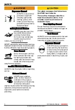
Page 35: ...ath or serious injury Sever Hazard NEVER wear jewelry unbuttoned cuffs ties or loose fitting clothing and ALWAYS tie long hair back when working near moving rotating parts Keep hands feet and tools away from all moving parts Always remove any tools or shop rags used during maintenance from the area before operation NEVER service the Sail Drive while under tow or if the engine is running at idle sp...

Page 36: ...roded connectors CAUTION The safety messages that follow have CAUTION level hazards These safety messages describe a hazardous situation which if not avoided could result in minor or moderate injury Slipping and Tripping Hazard Ensure that adequate floor space is set aside for servicing Sail Drive The floor space must be clean flat and free of spilled liquids and debris to prevent slipping or trip...

Page 37: ...air the marine gear s safety and performance characteristics and shorten the Sail Drive s life Any alterations to this Sail Drive may affect the warranty coverage of your Sail Drive TIGHTENING FASTENERS Use the correct amount of torque when tightening fasteners Applying excessive torque may damage the fastener or component and too little torque may cause a leak or component failure The tightening ...

Page 38: ...6 5 0 8 lb ft 20 6 2 0 N m 15 2 1 5 lb ft 39 2 2 0 N m 28 9 1 5 lb ft 70 6 4 9 N m 52 1 3 6 lb ft 109 8 4 9 N m 81 0 3 6 lb ft 180 3 10 0 N m 133 0 7 4 lb ft Standard Torque Chart Thread size Pitch mm M6 1 0 M8 1 25 M10 1 5 M12 1 75 M14 1 5 M16 1 5 Tightening Torque lb in 96 0 9 0 lb ft 19 0 2 0 36 0 4 0 65 0 7 0 101 0 7 0 167 0 7 0 N m 10 8 1 0 25 5 2 9 49 0 4 9 88 3 9 8 137 0 9 8 226 0 9 8 kgf m...

Page 39: ...ive Hours and Daily Checks Keep a log of the number of hours the Sail Drive is run each day and a log of the daily checks performed Also note the date type of repair e g replaced bearings and parts used for any service needed between the periodic maintenance intervals Failure to perform periodic maintenance will shorten the life of the Sail Drive Yanmar Replacement Parts Yanmar recommends that you...

Page 40: ...ation Change Lubricating Oil First SD20 SD50 SD50 4T Cooling Water Open Close Cooling Water Cock Before after operation Clean Cooling Water Suction Hole Drain Cooling Water After operation Remote Control System Inspect Remote Control Device Cone Clutch and Shifter Inspect replace or lap Replace the cone clutch Anode Inspect And Replace Anode Lower Case Repair Case Coating Boat Hull Water Tightness...

Page 41: ...ks on page 23 50 Hours Or After 1 Month Every 100 Hours Every 250 Hours Every 500 hours Every Year Every 2000 Hours Every 5 Years Flexible Mount Inspect and or replace the flexible mount mounting height Replace the flexible mount PERIODIC MAINTENANCE SD Operation Manual 37 2009 Yanmar Marine International ...

Page 42: ...inum outboards or stern drives Follow the manufacturer s directions for surface preparation and application Contact your authorized Yanmar Marine dealer or distributor for assistance Inspecting the Anode See Inspecting and Replacing the Anode on page 48 Inspecting The Folding Propeller Confirm that the blade of the folding propeller opens smoothly Inspect for wear on the blade fixing pins replacin...

Page 43: ...rain plug and the upper gear case oil dipstick CAUTION Let the drive unit cool at least 5 minutes after operation before removing the oil drain plug Hot oil could spurt out forcefully if the drain plug is removed from the drive unit immediately after operation SD20 1 2 3 4 0005450 Figure 2 1 Dipstick 2 Upper Gear Case 3 Lower Gear Case 4 Lubricating Oil Drain Plug Inspecting and Replacing the Clut...

Page 44: ...ve unit cool at least 5 minutes after operation before removing the oil drain plug Hot oil could spurt out forcefully if the drain plug is removed from the drive unit immediately after operation SD50 SD50 4T 0005451 1 2 3 Figure 3 1 Dipstick 2 Plug 3 Drain Plug PERIODIC MAINTENANCE 40 SD Operation Manual 2009 Yanmar Marine International ...

Page 45: ...erCruiser on bottle MerCruiser Part code 91 85729A1 1 Adapter joint 196311 92960 1 Thread std M10 x 1 5 maximum length 12 mm O ring for adapter 24311 000100 1 Stiff rubber hoses 2 Inner diameter 14 to 16 mm 0 5 to 0 625 in plus hose clamps If Yanmar part is used part code is 196440 92970 Compressor set 1 Hand pump 28210 000080 1 Optional parts When vessel is out of the water 2 are required PERIODI...

Page 46: ...h the bucket or pump If a Yanmar original rubber hose is to be used thepartnumberis196440 92970 Removing Oil 1 0005453 2 3 Figure 5 1 Plug 2 Air Pressure Hose 3 Adapter Joint Fastest Way Blowing Out by using Air Pressure Note Use Compressed Air 0 5 to 1 Bar 7 25 to 14 5 psi from main system 12 V portable compressor or from portable hand pump or foot pump WARNING ALWAYS wear safety glasses when usi...

Page 47: ...ely 12 minutes Using Yanmar Pump Refer to Preparing the Sail Drive on page 42 and Fastest Way Blowing Out by using Air Pressure on page 42 0005455 Figure 7 Connect the hand pump with hoses as shown above Figure 7 and start pumping Be aware that oil has to flow down through restricted parts of the casing and then back up again so pressure will initially be high and pumping will be difficult Pausing...

Page 48: ...ruiser 3 Connect the hose with a hose clip to the adapter joint below the shift lever 4 Remove the plug from the upper case cover Figure 8 1 5 Operate the pump to fill the Sail Drive with oil After bottle is empty change the bottle while the pump and hose remain connected to the adapter joint 6 After filling first screw in and tighten the plug at the top cover Figure 8 1 Then remove the oil bottle...

Page 49: ...screw in and tighten the plug at the top cover Then remove the hand pump hose and adapter joint and screw in the oil plug with a gasket Not Using Pump Refer to Filling With Lubricating Oil SD20 SD50 and SD50 4T on page 19 When The Vessel Is Out Of The Water Preparing The Sail Drive 0005457 1 Figure 10 1 Plug 1 Remove the bottom drain plug 2 Screw in the adapter joint with the O ring When using own...

Page 50: ...are that oil is divided into two channels connected by the lower gear and lower drain port Replacing Oil Refer to Filling With Lubricating Oil SD20 SD50 and SD50 4T on page 19 Using MerCruiser Pump or simple market pump Refer to Preparing The Sail Drive on page 45 0005459 2 3 1 Figure 12 1 Plug 2 O Ring 3 Adapter Joint 1 Use a MerCruiser pump with like the one shown above Figure 12 or use a simila...

Page 51: ...ware that oil has to flow up through restricted parts of the drive so pumping will be hard Waiting a few minutes will help After pumping in about 1 L 1 1 qt of oil screw in the oil changing plug Be aware that the drain hose can easily slip out of the bucket and cause oil spilling The hand pump and rubber hose are available from Yanmar and are optional parts for SD50 SD50 4T Any type of hand pump o...

Page 52: ...d on the sail drive SD20 while the boat in the water ANODE 196420 02441 1 3 2 4 5 019416 01X Figure 15 1 Safety Label 2 Anode 3 Anode 4 Upper Gear Case 5 Lower Gear Case SD50 SD50 4T 1 2 0005463 Figure 16 1 Lower Gear Case 2 Anode An anode is provided on the lower gear case To inspect and replace the anode on the lower gear case the vessel must be removed from the water Note An optional two part a...

Page 53: ...Draining and Replacing Lubricating Oil SD50 SD50 4T on page 40 Inspecting and Replacing the Clutch Shifter See your authorized Yanmar dealer or distributor for procedure Every 500 Hours of Operation Inspecting and or Replacing the Cone Clutch Inspecting and or Replacing the Cone Clutch See your authorized Yanmar dealer or distributor for procedure PERIODIC MAINTENANCE SD Operation Manual 49 2009 Y...

Page 54: ...acing Rubber Diaphragm Seal Ring Rubber diaphragms A and B SD20 SD50 SD50 4T The rubber diaphragms A and B of the Sail Driveareimportantpartsforthehulland crew safety Since rubber degenerates during use be sure to inspect them every two years The vessel must be lifted onto a block for this procedure To replace consult your Yanmar Marine dealer Inspecting Seal Sensor See Figure 9 on page 22 See you...

Page 55: ...r for procedure Flexible Mount must be replaced every 2000 hours Replacing the Cone Clutch See your authorized Yanmar dealer or distributor for procedure Every 5 Years Replacing Rubber Diaphragm Seal Ring Replacing Rubber Diaphragm Seal Ring To replace consult your Yanmar Marine dealer PERIODIC MAINTENANCE SD Operation Manual 51 2009 Yanmar Marine International ...

Page 56: ...This Page Intentionally Left Blank PERIODIC MAINTENANCE 52 SD Operation Manual 2009 Yanmar Marine International ...

Page 57: ...2 5 L 2 4 qt 2 35 L Extension 58 2 5 qt 2 45 L Extension 100 2 6 qt Dry Weight 30 kg 66 lb 39 kg 86 lb 41 kg 90 lb Remote Control Device Control Head Single control lever Cable MORSE 33C equivalent Applicable Engine Model Maximum Rated Out put Power At Crankshaft 1GM10C 6 7 kW 9 1 hp 3600 rpm 2YM15 10 3 kW 14 hp 3600 rpm 3YM20 16 2 kW 22 hp 3600 rpm 3YM30 22 1 kW 30 hp 3600 rpm 3JH4CE 28 7 kW 39 h...

Page 58: ...This Page Intentionally Left Blank SPECIFICATIONS 54 SD Operation Manual 2009 Yanmar Marine International ...

Page 59: ...hite W R White Red L R Blue Red W B White Black R B Red Black Allowable length by cross sectional area of battery cable Section of cable mm2 in 2 Allowable length L 1 2 3 m ft 15 0 023 0 86 0 26 20 0 031 1 3 0 40 30 0 046 2 3 0 70 40 0 062 2 8 0 85 50 0 077 3 5 1 07 60 0 093 4 1 1 25 SD Operation Manual 55 2009 Yanmar Marine International ...

Page 60: ...S R W W L B W L Y W W R B O L R W B R W L B W L Y W R B B O L R L W R R W L B W L Y W R B W R R B W R B R B R B R B R 30 AC 22 21 20 26 0005465 18 13 14 16 15 12 11 10 9 8 3 4 7 17 6 1 5 2 23 24 25 Figure 1 SYSTEM DIAGRAMS 56 SD Operation Manual 2009 Yanmar Marine International ...

Page 61: ...d 18 Sail Drive extension cable 0 3 m 1 ft 19 Not used Except 1GMC 20 Key switch 21 Push button switch 22 Charge lamp 23 Cooling Water temp lamp 24 Engine Oil pressure lamp 25 Rubber seal lamp Sail Drive 26 Buzzer Note If the cross sectional area of the wire being used is equal to or less than 20 mm2 approximately AWG 4 the combined lengths of items 1 2 and 3 must be less than 2 5 m 8 2 ft If the ...

Page 62: ...L B W L Y W W R B O L R W B R B Y W W R R B W L L B W R B L B O B R B W R Y W W L R B R W L B W L Y W R B B O L R L P P R W L B R B 2 6 19 14 15 17 28 16 18 13 7 4 23 24 25 26 12 30 AC 21 20 22 27 R B L B W W R B W L R B W R R B Y W 5 Figure 2 SYSTEM DIAGRAMS 58 SD Operation Manual 2009 Yanmar Marine International ...

Page 63: ...sion cable 0 3 m 19 Not used Except 1GMC 20 Light switch 21 Key switch 22 Push button switch 23 Charge lamp 24 Cooling Water temp lamp 25 Engine Oil pressure lamp 26 Rubber seal lamp Sail Drive 27 Buzzer 28 Tachometer Note If the cross sectional area of the wire being used is equal to or less than 20 mm2 approximately AWG 4 the combined lengths of items 1 2 and 3 must be less than 2 5 m 8 2 ft If ...

Page 64: ...3 m 30 mm 2 40 mm 2 2 8 m 3 5 m 50 mm 2 2W 2R 60 mm 2 4 1 m G1 P G2 30 L L R O B YW WL YG LB R L L R O B YW WL YG LB G1 G2 30 17 AC W 17 AC W P 3W 3L 3R YW RB WL LB O WG B YG WB YB GB YR GR WR G Y G2 17 GLOW OFF ON START Key switch 30 AC G1 WBr WBr W Y 3R B 1 2 3 10 11 12 15 15 17 18 16 19 20 20 21 22 23 24 25 26 28 29 24 30 30 31 32 33 27 16 13 4 5 6 7 8 9 2 3 10 11 12 14 4 5 6 7 8 9 008433 00E 0...

Page 65: ... Lamps 3 Buzzer 4 Engine Oil Pressure 5 Coolant Temperature 6 Sail Drive Seal 7 Battery Low Charge Alarm 8 Fuse 3A 9 Stop Switch 10 Diodes 11 Key Switch 12 Tachometer Hour Meter 13 Instrument panel sub station Op tion 14 Instrument panel main station Op tion 15 Wire Harness 16 Relay 17 Wire Harness for Sub Panel 18 Amplifier Sail Drive Only 19 Procured by Customer 20 Battery 21 Battery Switch 22 E...

Page 66: ...2 8 m 3 5 m 50 mm 2 2W 2R 60 mm 2 4 1 m L L R O B YW WL YG LB G1 G2 30 17 AC W P 3W 3L 3R YW RB WL LB O WG B YG WB YB GB YR GR WR G Y G2 17 GLOW OFF ON START Key switch 30 AC G1 WBr W Y 3R B P WBr R L L R O WG G YG LB YB WB G1 G2 30 B WL YW 17 AC W WB YB GR B 1 2 3 10 11 12 15 15 17 18 38 16 19 20 20 21 22 23 24 25 26 28 29 24 30 30 31 32 33 39 40 27 16 13 4 5 6 7 8 9 2 3 10 11 12 37 36 14 34 35 6...

Page 67: ...Low Charge Alarm 8 Fuse 3A 9 Stop Switch 10 Diodes 11 Key Switch 12 Tachometer Hour Meter 13 Instrument Panel sub station Op tion 14 Instrument panel main station Op tion 15 Wire Harness 16 Relay 17 Wire Harness for Sub Panel 18 Amplifier Sail Drive Only 19 Procured by Customer 20 Battery 21 Battery Switch 22 Engine Stop Solenoid with VE Pump 23 Air Heater 24 Option 25 Stop Relay 26 Starter Relay ...

Page 68: ... 3 m 2 3 m 30 mm 2 40 mm 2 2 8 m 3 5 m 50 mm 2 2W 60 mm 2 4 1 m 17 G1 P G2 30 WBr AC R L L R W O B YW WL YG LB 2B 2B 5R 2W 2B 19 20 21 18 17 15 16 22 23 24 27 28 29 30 14 11 10 9 7 8 2 3 4 5 6 1 12 13 25 26 0 85B 128990 77910 119247 77100 120270 77511 119717 77800 0 85WBr 2R A A 3R 3W YW WL WG B RB LB O YG Key switch GLOW OFF ON START 30 AC G1 G2 17 3L 003880 00E Figure 5 SYSTEM DIAGRAMS 64 SD Ope...

Page 69: ... Switch 10 Instrument Panel 11 Tachometer Hour Meter 12 Wire Harness Option L 3M 13 Wire Harness Option L 6M 14 Amplifier only for Sail Drive 15 Relay 16 Glow Plug 17 Engine Stop Solenoid 18 Battery Switch 19 Allowable Length by Cross Sectional Area of Battery Cable 20 Procured by Customer 21 Battery 22 Stop Relay 23 Starter Relay 24 Starter 25 Coolant Temperature Switch 26 Engine Oil Pressure Swi...

Page 70: ...Y WR YB GB G GR Key switch GLOW OFF ON START 30 AC G1 G2 17 3L A A 31 L B O P 40 39 37 38 36 35 34 20 19 44 45 46 47 48 49 41 43 17 AC 30 G1 G2 LB B L YG RB 12V 2R 2B 2B 5R 3L Option WBr WL YW B W Y 2R 2W S B 3R 10B 10R Y O B B E B E R L RB LB RB LB RB YG LB R L 5R 12V 33 32 22 21 26 27 28 29 30 23 24 25 003881 00E Figure 6 SYSTEM DIAGRAMS 66 SD Operation Manual 2009 Yanmar Marine International ...

Page 71: ...m 17 Water in Sail Drive Seal Alarm 18 Battery Low Charge Alarm 19 Option 20 Alarm Lamps 21 Air Heater Option 22 Engine Stop Solenoid 23 Stop Relay 24 Starter Relay 25 Starter 26 Coolant High Temperature Switch 27 Engine Oil Low Pressure Switch 28 Alternator Option 29 Alternator 30 Water in Sail Drive Seal Sensor on Sail Drive 31 Water in Sail Drive Seal Sensor Am plifier Sail Drive Only 32 Batter...

Page 72: ...G B RB LB O YG WB YR Y WR YB GB G GR Key switch GLOW OFF ON START 30 AC G1 G2 17 3L A A 31 L B O P 17 AC 30 G1 G2 LB 20 WB WL 19 YB YW B L YG RB 12V 2R 2B 2B 5R 3L WBr WL YW B W Y 2R 2W S B 3R 10B 10R Y O B B E B E R L RB LB RB LB RB YG LB R L 5R 12V 33 32 22 50 51 53 52 54 48 49 21 26 27 YB WB 34 35 28 29 30 23 24 25 003882 00E Figure 7 SYSTEM DIAGRAMS 68 SD Operation Manual 2009 Yanmar Marine In...

Page 73: ...gine Oil Pressure Meter 20 Coolant Temperature Meter 21 Air Heater Option 22 Engine Stop Solenoid 23 Stop Relay 24 Starter Relay 25 Starter 26 Coolant High Temperature Switch 27 Engine Oil Low Pressure Switch 28 Alternator Option 29 Alternator 30 Water in Sail Drive Seal Sensor on Sail Drive 31 Water in Sail Drive Seal Sensor Am plifier Sail Drive Only 32 Battery Option 33 Battery 34 Engine Oil Pr...

Page 74: ...WBr 2B 5R B L E LB RB R LB RB Option Relay W Y B 5R B Y 12V 1 3 2 R WBr P Wire harness 3R Alarm lamps Fuse 3A Alarm lamps B A A L YG RB only for sail drive only for sail drive 2W 2R diodes Instrument panel main station Option G1 P G2 30 WBr diodes L L R O B YW WL YG LB R L L R O B YW WL YG LB G1 G2 30 17 AC W 17 AC W R P B 4JH4AE only 4 5 6 7 8 10 2 1 3 9 14 15 16 17 18 12 11 13 31 33 32 22 21 26 ...

Page 75: ...l 10 Fuse 3A 11 Starter Switch 12 Stop Switch 13 Tachometer Hour Meter 14 Buzzer 15 Lubricating Oil Low Pressure Alarm 16 Coolant High Temperature Alarm 17 Water in Sail Drive Seal Alarm 18 Battery Low Charge Alarm 19 20 21 Air Heater 22 Engine Stop Solenoid 23 Stop Relay 24 Starter Relay 25 Starter 26 Coolant High Temperature Switch 27 Engine Oil Low Pressure Switch 28 Alternator Optional 29 Alte...

Page 76: ...ess 3R Alarm lamps B A A L YG RB only for sail drive only for sail drive 2W 2R diodes Instrument panel main station Option P WBr Fuse 3A Alarm lamps diodes L L R W O B YW WL YG LB R L L R O WG G YG LB YB WB G1 G2 30 B WL YW 17 AC W 4JH4AE Only P B R 4 5 6 7 8 10 2 1 3 9 14 15 16 17 18 12 11 13 20 19 31 33 32 22 21 26 27 28 29 30 36 34 35 23 24 25 3W 3L 3R YW RB WL LB O WG B YG WB YB GB G YR GR WR ...

Page 77: ... Meter 14 Buzzer 15 Seawater 16 Fuel Filter 17 Water in Sail Drive Seal Alarm 18 Battery Low Charge Alarm 19 Engine Oil Pressure Meter Alarm 20 Coolant Temperature Meter Alarm 21 Air Heater 22 Engine Stop Solenoid 23 Stop Relay 24 Starter Relay 25 Starter 26 Coolant High Temperature Switch 27 Engine Oil Low Pressure Switch 28 Alternator Optional 29 Water in Sail Drive Seal Sensor on Sail Drive 30 ...

Page 78: ...5RB 0 85YW 0 85WL 0 85 O 0 85YG R 2L 12V 1 3 2 10R 10B 0 85B 2B 2R WBr 2B 5R W Y B 3BR B Y B L YG RB 2W 2B 2B 5R 2W 2B 0 85B 119717 119247 77100 120270 77511 128990 77910 77800 0 85WBr 2R A A 3R 3W YW WL WG B RB LB O YG 3L P O 0 0 47Ω 3W 1N4007 L WBr W R L YW R B YW WL YG LB RB RB RB B B RB II II I I Figure 10 SYSTEM DIAGRAMS 74 SD Operation Manual 2009 Yanmar Marine International ...

Page 79: ...rmeter 14 Instrument Panel Main Station Op tion 15 Wire Harness 16 Wire Harness for Sub Panel 17 Water in Sail Drive Seal Sensor Amplifier Sail Drive Only 18 Procured by Customer 19 Battery 20 Battery Switch 21 Engine Stop Solenoid 22 Relay 23 Glow Plug 24 Stop Relay 25 Starter Relay 26 Starter 27 Coolant High Temperature Switch 28 Engine Oil Pressure Switch 29 Alternator 30 Ground Bolt 31 Sail Dr...

Page 80: ... 0 0 47Ω 3W 1N4007 WBr W L WBr W R L R L YW YW R B YW WL YG LB YW WL YG LB RB RB RB RB RB RB L B YG O LB RB WB YB WBr 2L W R YW WL R RB B B B B RB R P B 3W 3L 3R YW RB WL LB O WG B YG WB YB GB G YR GR WR Y II I II I II I II I 21 22 16 16 3 1 2 4 5 6 7 9 10 11 12 12 8 3 2 4 5 6 7 9 10 11 12 12 8 24 25 23 26 27 31 32 31 29 30 28 21 13 14 13 15 34 35 33 19 17 17 18 20 Figure 11 SYSTEM DIAGRAMS 76 SD ...

Page 81: ...Coolant High Temperature Alarm 6 Water in Sail Drive Seal Alarm 7 Battery Low Charge Alarm 8 Fuse 3A 9 SWITCH GLOW I OFF 0 STOP II 10 SWITCH START II ON I OFF 0 11 Diodes 12 Switch 13 Tachometer Hourmeter 14 Instrument Panel Sub Station Op tion 15 Instrument Panel Main Station Op tion 16 Relay 17 Wire Harness 18 Wire Harness for Sub Panel 19 Water in Sail Drive Seal Sensor Am plifier Sail Drive On...

Page 82: ... WBr W L WBr W R L R L YW YW R WG G YG LB YW WL YG LB R RB R RB RB RB RB L B YG O LB RB WB YB WBr 2L W R YW WL R WL WB YW R WL YW B B B R B B B WB YB RB R P B 3W 3L 3R YW RB WL LB O WG B YG WB YB GB G YR GR WR Y II I II I 21 21 23 25 26 27 32 31 31 19 13 14 15 16 16 20 17 17 18 3 9 10 11 12 12 8 1 2 4 5 6 7 13 3 9 10 11 12 12 8 2 36 37 6 7 40 34 41 35 28 24 33 29 30 22 38 39 Figure 12 SYSTEM DIAGR...

Page 83: ...larm 8 Fuse 3A 9 SWITCH GLOW I OFF 0 STOP II 10 SWITCH START II ON I OFF 0 11 Diodes 12 Switch 13 Tachometer Hourmeter 14 Instrument Panel Sub Station Op tion 15 Instrument Panel Main Station Op tion 16 Relay 17 Wire Harness 18 Wire Harness for Sub Panel 19 Water in Sail Drive Seal Sensor Am plifier Sail Drive Only 20 Procured by Customer 21 Battery 22 Battery Switch 23 Engine Stop Solenoid 24 Air...

Page 84: ...MAINTENANCE LOG Date Operating Hours Maintenance Performed Dealer Name Stamp or Signa ture SYSTEM DIAGRAMS 80 SD Operation Manual 2009 Yanmar Marine International ...

Page 85: ...Date Operating Hours Maintenance Performed Dealer Name Stamp or Signa ture SYSTEM DIAGRAMS SD Operation Manual 81 2009 Yanmar Marine International ...

Page 86: ...This Page Intentionally Left Blank SYSTEM DIAGRAMS 82 SD Operation Manual 2009 Yanmar Marine International ...

Reviews: