background image

SK1050

Yanmar® 3TNV88C

Operator’s

Manual

CMW®

053-2963

Issue 3.0

Original Instruction

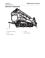
Summary of Contents for SK1050

Page 1: ...SK1050 Yanmar 3TNV88C Operator s Manual CMW 053 2963 Issue 3 0 Original Instruction ...

Page 2: ...ication 3 Machine Components 4 Operator Orientation 5 Operating Area 5 About This Manual 6 Bulleted Lists 6 Numbered Lists 6 California Proposition 65 Diesel engine exhaust and some of its constituents are known to the State of California to cause cancer birth defects and other reproductive harm www P65warnings ca gov ...

Page 3: ...al Serial Number Location Serial Number Location Record serial number and date of purchase in spaces provided Serial number is located as shown Item Date of manufacture Date of purchase Machine serial number t53om001h eps t53om001h eps ...

Page 4: ...tures Use in any other way is considered contrary to the intended use This machine should be operated serviced and repaired only by professionals familiar with its particular characteristics and acquainted with the relevant safety procedures Equipment Modification This equipment was designed and built in accordance with applicable standards and regulations Modification of equipment could mean that...

Page 5: ...Overview 4 SK1050 Operator s Manual Machine Components Machine Components 1 Operator station platform 2 Tracks 3 Engine compartment 4 Lift arms 5 Attachment plate 1 2 3 4 5 t53om002h eps t53om002h eps ...

Page 6: ...n Operator Orientation 1 Front 2 Right side 3 Rear 4 Left side Operating Area Operator should stand only in the location shown IMPORTANT Top view of machine is shown IMPORTANT Top view of machine is shown 1 2 3 4 t53om003h eps t53om003h eps t62om004w19 eps ...

Page 7: ...achine Cross references such as See page 50 will direct you to detailed procedures Bulleted Lists Bulleted lists provide helpful or important information or contain procedures that do not have to be performed in a specific order Numbered Lists Numbered lists contain illustration callouts or list steps that must be performed in order ...

Page 8: ...contact your Ditch Witch dealer If you need assistance in locating a dealer visit our website at www ditchwitch com or write to the following address The Charles Machine Works Inc ATTN Marketing Department PO Box 66 Perry OK 73077 0066 USA The descriptions and specifications in this manual are subject to change without notice The Charles Machine Works Inc reserves the right to improve equipment So...

Page 9: ...Issue number 3 0 OM 1 20 Part number 053 2963 Copyright 2016 2018 2020 by The Charles Machine Works Inc and Ditch Witch are registered trademarks of The Charles Machine Works Inc This product and its use may be covered by one or more patents at http patents charlesmachine works ...

Page 10: ...res for preparing jobsite preparing operator and preparing equipment Controls 31 Machine controls gauges and indicators and how to use them Drive 49 Procedures for startup cold start driving and shutdown Transport 55 Procedures for lifting hauling and retrieving Complete the Job 63 Procedures for restoring the jobsite and rinsing and storing equipment Service 65 Service intervals and instructions ...

Page 11: ...Contents 10 SK1050 Operator s Manual Support 95 The warranty policy for this machine and procedures for obtaining warranty consideration and training ...

Page 12: ... 12 Emergency Procedures 13 Electric Strike Description 13 If an Electric Line is Damaged 14 If a Gas Line is Damaged 14 If a Fiber Optic Cable is Damaged 14 If Machine Catches on Fire 14 Safety Alert Classification 15 Machine Safety Alerts 16 For additional precautions see Prepare chapter ...

Page 13: ...re work begins Safety videos are available from your Ditch Witch dealer or at www ditchwitch com safe Safety Data Sheets SDS are available at www ditchwitch com support Fully inspect equipment before operating Repair or replace any worn or damaged parts Replace missing or damaged safety shields and safety alert signs Contact your Ditch Witch dealer for assistance Follow instructions on all safety ...

Page 14: ...st resistance Pipes hoses and cables will conduct electricity back to all equipment Low voltage current can injure or kill Many work related electrocutions result from contact with less than 440 volts Most electric strikes are not noticeable but indications of a strike include power outage smoke explosion popping noises arcing electricity If any of these occur assume an electric strike has occurre...

Page 15: ... depend on the situation Immediately shut off engine s if this can be done safely and quickly Remove any ignition source s if this can be done safely and quickly Warn others that a gas line has been cut and that they should leave the area After warning others to leave the area leave jobsite as quickly as possible Immediately call your local emergency phone number and utility company If jobsite is ...

Page 16: ...this entire section before using your equipment Watch for the three safety alert levels DANGER WARNING and CAUTION Learn what each level means indicates a hazardous situation that if not avoided will result in death or serious injury This signal word is to be limited to the most extreme situations indicates a hazardous situation that if not avoided could result in death or serious injury indicates...

Page 17: ...chine Safety Alerts Machine Safety Alerts 1 Lift point See Transport chapter for more information 2 Tiedown location See Transport chapter for more information 3 Pre heater Fire or explosion can cause death or serious injury Never use starter fluid ...

Page 18: ...t with locking device Use correct equipment and procedures 7 Hot parts Contact can cause burns Only touch when cool or wear gloves 8 Lifted load Crushing can cause death or serious injury Stay away from lifted load and its range of movement 9 Moving parts Contact can cause serious injury Stay away 10 Misuse of machine can cause death or serious injury Read and understand operator s manual and all ...

Page 19: ...Safety Awareness 18 SK1050 Operator s Manual Machine Safety Alerts ...

Page 20: ... 20 Select Start and End Points 20 Identify Hazards 21 Locate Utilities 22 Classify Jobsite 23 Arrange for Traffic Control 24 Prepare Operator 25 Prepare Equipment 26 Check Supplies 26 Check Equipment 26 Assemble Accessories 27 Connect Attachment 27 See Safety Awareness for additional precautions ...

Page 21: ... site Consider how slope will affect setup and operation Assess the risks on each slope to determine if factors affecting risks create an unsafe condition for working See Slope Guidelines on page 55 Space Check that starting and ending points allow enough space for working Comfort Consider shade wind fumes and other site features Underground utilities Contact can cause death or serious injury Loca...

Page 22: ...stacles such as buildings railroad crossings or streams signs of utilities traffic access soil type and condition loose material such as fencing or cable Identify safety hazards and classify jobsite if attachment will penetrate ground See Classify Jobsite on page 23 buried utility notices gas or water meters drop boxes manhole covers utility facilities without overhead lines junction boxes light p...

Page 23: ...ice contact all local utility companies to have underground utilities located Verify Underground Utilities Have an experienced locating equipment operator sweep area within 20 6 m to each side of proposed excavation to verify previously marked line and cable locations Mark location of all buried utilities and obstructions Locate Overhead Lines Note location and height of all overhead lines in jobs...

Page 24: ...eful hand digging or soft excavation Have service shut down while work is in progress Have electric company test lines before returning them to service Natural Gas Jobsite Precautions Position equipment upwind from gas lines and use one or both of these methods Expose line by careful hand digging or soft excavation Have service shut down while work is in progress Have gas company test lines before...

Page 25: ...ns You may need to use different methods to safely avoid other underground hazards Talk with those knowledgeable about hazards present at each site to determine which precautions should be taken or if job should be attempted Clear objects such as landscaping fabric cable and wire from the work area These objects may be underground or partially buried Arrange for Traffic Control Vehicle and pedestr...

Page 26: ... at www ditchwitch com safe Safety Data Sheets SDS are available at www ditchwitch com support Use equipment carefully Stop operation and investigate anything that does not look or feel right Jobsite hazards Exposure can cause death or serious injury Use correct equipment and work methods Use and maintain appropriate safety equipment To help avoid injury Wear personal protective equipment includin...

Page 27: ...ent Fluid Levels fuel engine oil diesel exhaust fluid DEF if needed hydraulic fluid engine coolant Condition and Function all controls battery hoses and valves pumps and motors tires or tracks signs guards and shields filters air oil hydraulic fuel belts Improper control function Use can cause death or serious injury If control does not work as described in instructions stop machine and have it se...

Page 28: ...ind it to accommodate machine 2 Start engine 3 Tilt attachment plate 2 forward 4 Position attachment plate in upper lip of receiver plate 1 on attachment 5 Raise lift arms while tilting back attachment plate to engage pins NOTICE Use only Ditch Witch approved attachments Attachments can change the stability and operating characteristics of the machine See attachment operation manual for instructio...

Page 29: ...Prepare 28 SK1050 Operator s Manual Prepare Equipment 6 Ensure pins are engaged by rotating attachment down t43om007w eps ...

Page 30: ...on hoses Pressurized fluid or air Injection can cause death or serious injury Refer to operator s manual for correct use To help avoid injury Use a piece of cardboard or wood rather than hands to check for leaks Before disconnecting a hydraulic line turn engine off and operate all controls to relieve pressure Lower block or support any raised component with a hoist Cover connection with heavy clot...

Page 31: ... in manifold 6 Connect male coupler from attachment to female coupler 2 on machine 7 Connect female coupler from attachment to male coupler 1 on machine 8 If needed connect attachment case drain hose to case drain connector 3 9 For attachments that have a secondary function connect those hoses to the secondary circuit 4 5 10 Ensure that connections are secure by pulling on hoses 11 Select secondar...

Page 32: ...050 Operator s Manual Controls 31 Controls Chapter Contents Attachment Plate 32 Battery Disconnect 33 Display Version 1 34 Display Version 2 37 Gauges and Indicators 42 Miscellaneous 44 Operator Station 44 ...

Page 33: ...indicator To level bucket adjust until indicator is at top of sleeve To level other attachments adjust until level and mark indicator position on sleeve Use mark to indicate level with that attachment 2 Attachment latch To lock attachment move latch down To unlock attachment move latch up t43om034w eps 1 2 ...

Page 34: ...t Item Description IMPORTANT Battery disconnect switch To disconnect move left To connect move right NOTICE Do not disconnect with engine running To avoid equipment damage wait two minutes after turning engine off before disconnecting battery t53om033w20 eps c00ic156w eps _ ...

Page 35: ...8 Engine coolant temperature gauge 9 Exhaust cleaning disabled indicator 10 Hourmeter 11 Tachometer 12 Throttle mode indicator 13 Tachometer setpoint indicator 14 Voltmeter gauge 15 Engine load gauge Item Description IMPORTANT 1 High exhaust temperature indicator Lights when exhaust temperature is high IMPORTANT Will light during exhaust cleaning t53om057w20 eps STOP 125 15 20 10 RPMx100 25 30 5 2...

Page 36: ...hts when exhaust cleaning is needed 8 Engine coolant temperature gauge Displays engine coolant temperature 9 Exhaust cleaning disabled indicator Lights when operator has disabled exhaust cleaning NOTICE Failure to complete an exhaust cleaning when required can cause engine damage 10 Hourmeter Displays engine operating time Use these times to schedule service 11 Tachometer Displays engine speed 12 ...

Page 37: ...ttle up control To increase engine speed setpoint when in autothrottle mode press 5 Throttle down control To decrease engine speed setpoint when in autothrottle mode press t53om058w20 eps STOP 125 15 20 10 RPMx100 25 30 5 230 32 190 150 110 F 70 0 30 0 0 0V Tier4 0 35 100 75 50 25 0 Engine STARTUP Load 0 HRS 1 2 3 4 5 STOP 125 15 20 10 RPMx100 25 30 5 230 32 190 150 110 F 70 0 30 0 0 0V 0 35 100 7...

Page 38: ...il pressure gauge 8 Engine warning stop indicator 9 High exhaust temperature indicator 10 Exhaust cleaning indicator 11 Exhaust cleaning disabled indicator 12 Engine coolant temperature gauge 13 Voltmeter gauge 14 Real time clock 15 Tachometer Item Description IMPORTANT 1 Tachometer setpoint indicator Indicates target engine speed Set by operator 1 15 2 4 5 6 7 8 9 10 11 3 14 12 13 t53om011w20 eps...

Page 39: ...ights when engine oil pressure is too high 8 Engine warning stop indicator Lights when engine needs attention Lights when operator needs to stop engine 9 High exhaust temperature indicator Lights when exhaust temperature is high IMPORTANT Will light during exhaust cleaning 10 Exhaust cleaning indicator Lights when exhaust cleaning is needed 11 Exhaust cleaning disabled indicator Lights when operat...

Page 40: ... press 2 Main menu key To select main menu press 3 Throttle down control To decrease engine speed when in display throttle mode press 4 Throttle up control To increase engine speed when in display throttle mode press 1 2 3 4 t53om007w20 eps 5 10 x100 RPM 15 20 30 0000 25 00000 10 10 15 0v F 000 000 5 10 x100 RPM 15 20 30 0000 25 00000 10 10 15 0v F 000 000 ...

Page 41: ... key 5 Machine settings key 6 Previous selection key 7 Next selection key 8 Select key 9 Return key Item Description IMPORTANT 1 Brightness key To change brightness of display press 2 User settings menu key To customize settings press Language real time clock and units of measurement can be adjusted in this screen t53om009w20 eps 1 2 3 4 5 6 7 8 9 ...

Page 42: ...aust cleaning information press Parked cleanings can be initiated and automatic exhaust cleanings can be enabled disabled in this screen 5 Machine settings key To customize settings press Throttle mode and ride control speed can be adjusted in this screen 6 Previous selection key To scroll to previous menu selection press 7 Next selection key To scroll to next menu selection press 8 Select key To ...

Page 43: ...nual Gauges and Indicators Gauges and Indicators Item Description IMPORTANT 1 Hydraulicfluid level sight glass Shows level of hydraulic fluid in tank 2 Fuel gauge Displays level of fuel See Approved Fuel on page 70 t53om004w20 eps 1 2 ...

Page 44: ...l Controls 43 Miscellaneous Miscellaneous Item Description IMPORTANT 1 Graphic display Displays graphic symbols for indicators and conditions 2 Auxiliary outlet Provides power for other equipment 12VDC 5A t53om008w20 eps 1 2 ...

Page 45: ...ntrol Track drive joystick 2 Right track drive control Track drive joystick 3 Parking brake switch 4 Throttle 5 Ignition switch 6 Worklight switch 7 Lift arm control 8 Attachment drive control 9 Auxiliary circuit switch 10 Auxiliary lock control If equipped t53om005w20 eps 1 2 3 4 5 6 7 8 9 10 ...

Page 46: ...ick To drive forward push To drive in reverse pull To go faster in any direction move farther from neutral position To steer move left or right 3 Parking brake To set press bottom To release press top 4 Throttle To increase engine speed push To decrease pull Control only functions if console throttle mode is selected See Main Menu on page 40 If throttle is not set to low when engine is started or ...

Page 47: ...n off press bottom 7 Lift arm control To move lift arms down push To float push to end To move lift arms up pull To curl attachment up move left To curl attachment down move right 8 Attachment drivecontrol To move attachment in reverse push To move attachment forward pull Use auxiliary lock control to lock auxiliary function See Auxiliary lock control on page 47 Item Description IMPORTANT c00ic377...

Page 48: ...h To toggle between primary 1 and secondary 2 auxiliary circuits press Use this control based on attachment selection See Hydraulic Connection on page 29 10 Auxiliary lock control To lock auxiliary function press pedal To unlock release Item Description IMPORTANT c00ic226w eps 1 2 ...

Page 49: ...Controls 48 SK1050 Operator s Manual Operator Station ...

Page 50: ...e Chapter Contents Start 50 Operate 51 Slope Guidelines 52 Reduce Track Wear 53 Shut Down 53 For additional precautions see Safety Awareness and Prepare chapters IMPORTANT For more information on how to operate controls see Controls chapter ...

Page 51: ...le until controls operate as described in controls chapter EMERGENCY SHUTDOWN Shut off machine or press remote engine stop button if equipped Misuse of machine can cause death or serious injury Read and understand operator s manual and all other safety instructions before use Know how to use all controls To help avoid injury Allow hydraulic fluid time to warm before operating in cold weather Cold ...

Page 52: ...peration manual for instructions regarding proper operation of attachments NOTICE Drive carefully in congested areas Know machine s clearance and turning radius Survey field of vision when operating machine EMERGENCY EXIT Release controls and step off platform IMPORTANT If needed for attachment operation lock auxiliary function See Auxiliary lock control on page 47 ...

Page 53: ...accordingly Maximum engine angle and braking performance are two absolute limits which must never be exceeded These maximums are stated below since they are design limits These design limits usually exceed the operating limits and must never be used alone to establish safe operating angle for variable conditions Maximum engine lubrication angle 20 Maximum service brake retarding force equal to tra...

Page 54: ...g with track edges pressed against hard walls or curbs operating on corrosive materials such as salt or fertilizer Shut Down 1 When job is complete move machine to level ground 2 Stop machine movement 3 Set parking brake 4 Lower lift arms to ground 5 Return all controls to neutral 6 Run engine at low throttle with no load for at least five minutes to cool 7 Shut off machine 8 If leaving machine un...

Page 55: ...Drive 54 SK1050 Operator s Manual Shut Down ...

Page 56: ... Contents Lift 56 Points 56 Procedure 56 Haul 57 Inspect Trailer 57 Load 58 Tie Down 59 Unload 60 Retrieve 60 For additional precautions see Safety Awareness and Prepare chapters IMPORTANT For more information on how to operate controls see Controls chapter ...

Page 57: ...s size and weight to lift as shown See Specifications on page 89 or measure and weigh equipment before lifting Lifted load Crushing weight can cause death or serious injury Stay away from lifted load and its range of movement To help avoid injury Only lift unit without attachment installed IMPORTANT Do not lift machine with attachments installed IMPORTANT Front of unit will be lower than rear t53o...

Page 58: ...hine can cause death or serious injury Read and understand operator s manual and all other safety instructions before use Know how to use all controls To help avoid injury Read trailer operator s manual before loading or transporting machine Ensure tow vehicle has proper tow capacity rating Attach trailer to vehicle before loading or unloading Load and unload trailer on level ground To help preven...

Page 59: ... 6 Drive forward slowly to move machine onto trailer until tiedown position is reached 7 Lower attachment to trailer bed 8 Set parking brake 9 Ensure all controls are in neutral position 10 Shut off machine 11 Tie down machine Horizontal movement Crushing can cause death or serious injury Read and understand operator s manual and all safety instructions before use To help avoid injury Start and op...

Page 60: ... truck or trailer at other points is unsafe and can damage machinery Procedure Loop a transport chain around each tie down point See chart below for correct distances between tiedown ends Ensure tiedowns are tight before transporting Distance US Metric A1 8 30 20 76cm A2 12 40 30 102cm t53om061w20 eps A1 A1 A1 A1 A2 A2 ...

Page 61: ... machine should not be towed If machine breaks down and retrieval is necessary Tow for no more than 100 30m at less than 1mph 1 6km h Use towing chains appropriately rated for maximum towing force Use maximum force of 1 5 times machine weight 1 Set parking brake 2 Block tracks to prevent machine from rolling Horizontal movement Crushing can cause death or serious injury Read and understand operato...

Page 62: ...hown facing towing vehicle 4 Loosen bypass valves shown three turns 5 Remove blocks 6 Release parking brake 7 After towing tighten bypass valve locknuts to 15 18ft lb 20 25N m NOTICE When bypass valves are open machine has no brakes t43om001w20 eps t43om002w20 eps t43om030w eps ...

Page 63: ...Transport 62 SK1050 Operator s Manual Retrieve ...

Page 64: ...1050 Operator s Manual Complete the Job 63 Complete the Job Chapter Contents Rinse Equipment 64 Disconnect Attachment 64 Stow Tools 64 For additional precautions see Safety Awareness and Prepare chapters ...

Page 65: ...e lock pins by lifting handles upward 4 Disconnect hydraulic hoses if used 5 Start engine 6 Tilt mount plate forward and back machine away from attachment Stow Tools Ensure all tools and accessories are loaded and properly secured on trailer NOTICE Do not spray water onto operator s console or electrical center in engine compartment Water can damage electrical components Wipe down instead Ensure a...

Page 66: ...Precaution 66 Welding Precaution 67 Working under Raised Lift Arms 67 Recommended Lubricants 68 Engine Oil Temperature Chart 69 Approved Coolant 69 Approved Fuel 70 Exhaust Cleaning 70 Service Interval Chart 71 Procedures 72 For additional precautions see Safety Awareness and Prepare chapters ...

Page 67: ...ace shield etc available for use depending on jobsite hazards or requirements Misuse of machine can cause death or serious injury Read and understand operator s manual and all other safety instructions before use Know how to use all controls To help avoid injury Unless otherwise instructed all service should be performed with the engine off and cool Lower unsecured raised components before servici...

Page 68: ...electronic components prior to welding on machine or attachments Connect welder ground close to welding point and make sure no electronic components are in the ground path Disconnect battery at battery disconnect switch before welding to prevent damage to battery Never turn off battery disconnect switch with engine running or alternator and other electronic equipment devices may be damaged Raised ...

Page 69: ...fications on page 89 For more information on engine lubrication and maintenance see your engine manual Item Description DEAC Diesel engine antifreeze coolant low silicate fully formulated meeting CES 14603 See Approved Coolant on page 69 DEO Diesel engine oil meeting or exceeding API service classification CJ 4 ACEA E6 or JASO DH 2 See viscosity chart API American Petroleum Institute ACEA European...

Page 70: ...om your Ditch Witch dealer as part number 255 1055 NOTICE Use only pre diluted coolant or concentrated coolant mixed with distilled water Do not use tap water Using water or high silicate automotive type coolant will lead to engine damage or premature engine failure Mixing heavy duty diesel engine coolant and automotive type coolants will lead to coolant breakdown and engine damage SAE 10W 30 SAE ...

Page 71: ...ble exhaust cleaning for the duration of the job and return to automatic cleaning when the job is finished The exhaust cleaning disabled icon will light and remain on until the system is returned to automatic cleaning mode The exhaust cleaning icon will light when the system is disabled and exhaust cleaning cycle is needed The icon will light when an automatic cleaning is needed If the area will a...

Page 72: ... test Change initial Lube initial Check Change Lube Service Startup 10 Hours 50 Hours 250 Hours 500 Hours 1000 Hours As Needed Auxiliary lock control Battery Belt fan Coolant Dust ejector valve Engine compartment Filter air Filter engine oil see Oil engine Filter fuel Filter hydraulic fluid Filter water separator Fluid hydraulic Fuse box Fuel hose Hydraulic hoses Intake air line Idler roller beari...

Page 73: ...ck cover 2 Loosen screw 2 until attachment drive control when attachment drive foot control is pressed down completely Lug nuts Oil engine Parking brake Radiator Hydraulic fluid cooler Track tension IMPORTANT If more resistance is needed open rear panel and lengthen clevis 1 Service Startup 10 Hours 50 Hours 250 Hours 500 Hours 1000 Hours As Needed t53om012w20 eps 2 1 ...

Page 74: ...ingle 12V maximum source for charging Never connect to rapid chargers or dual batteries Never lean over battery when making connections Never allow vehicles to touch when charging Never short circuit battery terminals for any reason or strike battery posts or cable terminals Refer to Safety Data Sheet SDS for additional information regarding battery NOTICE Electronic components can be easily damag...

Page 75: ... 3 Loosen and remove battery cable clamps carefully negative cable first 4 Clean cable clamps and terminals to remove dull glaze 5 Check for signs of internal corrosion in cables 6 Connect battery cable clamps positive cable first 7 Tighten any loose connections 8 Ensure that battery tiedowns are secure 9 Turn battery disconnect if equipped on t53om013w20 eps ...

Page 76: ...t of battery in service vehicle 9 Connect the other black negative cable clamp to engine or frame ground on disabled machine at least 12 305 mm from failed battery as shown 10 Operate service vehicle engine at 1500 2000 rpm for a few minutes to build an electrical charge in failed battery 11 Stop engine in service vehicle 12 Remove jumper cables from service vehicle black negative clamp first Do n...

Page 77: ...ion as needed 3 Tighten bolts 4 Check tension Change 1 Loosen two alternator bolts 1 2 2 Replace fan belt 3 Adjust position as needed 4 Tighten bolts 5 Check tension Coolant Check before startup and every 10 hours Change every 1000 hours Check Level 1 Check at overflow bottle 2 2 Add DEAC at fill 1 as needed to keep level at halfway point on overflow bottle Change 1 Remove plug 3 to drain 2 Instal...

Page 78: ...hours Ensure valve is not inverted damaged plugged or cracked Engine Compartment Check for debris every 10 hours Remove debris from engine compartment manually Do not use water or compressed air NOTICE Check more often if operating in large brush grassy conditions or if machine is being stored t53om016w20 eps t53om017w20 eps ...

Page 79: ... 5 Insert new primary element 6 Install cover with dust ejector 6 facing down 7 Reset air filter service indicator Filter Fuel Change filter shown every 500 hours If refueling from cans replace filters more often NOTICE Only open air filter housing when red band on indicator is visible Change the elements Do not attempt to clean them Improperly installed primary element can lead to premature engin...

Page 80: ...ded Check When red floating ring is raised drain Drain 1 Turn off at valve 1 2 Remove plug 2 to drain 3 Install plug 4 Turn on at valve 5 Start engine Filter will purge air from system Change 1 Turn off at valve 2 Remove plug to drain 3 Remove cover 3 4 Replace filter 4 5 Install cover 6 Install plug 7 Turn on at valve 8 Start engine Filter will purge air from system t53om020w20 eps 1 2 3 4 t53om0...

Page 81: ...lug 3 to drain 2 Install plug 3 Add THF at fill to keep level at halfway point on sight glass Fuel Hose Check fuel hose shown and clamp bands every 50 hours If clamp is loose apply oil to the threads and retighten If hose is worn replace Bleed fuel system if hose and or clamp is changed NOTICE Change every 250 hours if jobsite temperature exceeds 100 F 38 C more than 50 of the time IMPORTANT Ensur...

Page 82: ... s Manual Service 81 Procedures Fuse Box Check fuse box cover for damage before startup If cover is missing or damaged replace IMPORTANT Leave cover in place unless fuses are being checked or replaced t53om060w20 eps ...

Page 83: ...rather than hands to check for leaks Before disconnecting a hydraulic line turn engine off and operate all controls to relieve pressure Lower block or support any raised component with a hoist Cover connection with heavy cloth and loosen connector nut slightly to relieve residual pressure Catch all fluid in a container Before using system check that all connections are tight and all lines are unda...

Page 84: ...are properly seated by tightening castle nut 4 to 30 40ft lb 41 54N m while turning hub 5 Loosen and then hand tighten castle nut 6 Insert cotter pin into wheel spindle 3 7 Bend legs of cotter pin over top of spindle 8 Reassemble Tighten lug nuts to 80ft lb 108N m 9 Adjust track tension NOTICE Do not move hub after this step is complete NOTICE If hole is visible in slot but cotter pin cannot be in...

Page 85: ...eeded Oil Engine Check before startup and every 10 hours Change at 50 hours and every 250 hours thereafter Check Level 1 Check level at dipstick 4 2 Add DEO at fill 3 as needed to keep level at highest line on dipstick Change Oil and Filter 1 While oil is warm remove plug 1 to drain 2 Install plug 3 Remove filter 2 and replace with new filter 4 Add DEO at fill to keep level at highest line on dips...

Page 86: ...eded Check Check radiator shown for dirt grass and other debris Check radiator hoses for wear Check hose clamps for proper tightness Clean 1 Clean fins with compressed air or spray wash 2 Open rear hood and spray through radiator toward engine 3 If grease and oil are present on radiator spray with solvent and allow to soak overnight NOTICE Radiator may need to be cleaned more frequently in dusty o...

Page 87: ...dge A Distance should be 0 5 13mm Adjust 1 Lift track 2 Adjust tension To tighten pump MPG into grease zerk shown until distance measures 0 5 13mm To loosen remove zerk and drain all grease Then follow tightening procedure 3 Start engine 4 Drive forward one machine length and check track tension Contents under pressure Impact can cause death or serious injury Relieve pressure before opening To hel...

Page 88: ...d when gauge measures 700 900psi 48 62bar Adjust 1 Lift track 2 Remove gauge from stored location 3 Thread gauge into connection 4 Adjust tension To tighten pump MPG into grease zerk until gauge measures 700 900psi 48 62bar To loosen remove plug and drain all grease Then follow tightening procedure 5 Start engine 6 Drive forward one machine length and check track tension 1 2 t53om032w20 eps ...

Page 89: ...Service 88 SK1050 Operator s Manual Procedures ...

Page 90: ...SK1050 Operator s Manual Specifications 89 Specifications Chapter Contents SK1050 90 Declaration of Conformity 93 ...

Page 91: ... standard bucket 105 2667mm L Overall length of loader no attachment 86 2190mm Overall length of machine standard bucket 105 2680mm L2 Wheelbase track length 43 1092mm Ground clearance min center 7 4 188mm Ground clearance min side 3 7 94mm W Track width max 42 1065mm Track width min 36 915mm Unit width excluding tracks 35 838mm Bucket rollback angle full height 90 90 t35om026w eps L L2 A2 H2 H W ...

Page 92: ... 9 230mm tracks 4 9psi 0 33bar Machine weight no attachment fluids full 3435lb 1588kg Operating capacity 35 of tipping capacity 600lb 272kg Tipping capacity The rated operating capacity for this machine was determined using a standard bucket in the maximum reach position with center of gravity 7 18cm from the attachment plate Depending on the attachment the actual operating capacity of the attachm...

Page 93: ...8L min Pressure 3625psi 250bar Fluid Capacities US Metric Coolant 1 28gal 4 8L Engine oil with filter 5 0qt 4 7L Fuel tank 10 5gal 40L Hydraulic reservoir 9 2gal 35L Battery SAE reserve capacity 110min SAE cold crank 0 F 18 C 800amp 12V electrical system Vibration Levels Average vibration transmitted to the operator s hand during normal operation with a loader bucket is 2 5m sec2 Average vibration...

Page 94: ...ype Machine Type Engine Power xxx kW Serial Number i CMWXXXXXXXXXXXXXX Conforms to the requirements of 2006 42 EC Machinery Directive 2004 108 EC Electromagnetic Compatibility Directive 2000 14 EC Noise Emission Directive Measured sound power level Annex V XXXdBA Guaranteed sound power level Annex V XXXdBA The Technical Construction File is maintained at the manufacturer s location The manufacture...

Page 95: ...Specifications 94 SK1050 Operator s Manual Declaration of Conformity ...

Page 96: ...of Ditch Witch equipment Always give model serial number and approximate date of your equipment purchase This information should be recorded and placed on file by the owner at the time of purchase Return damaged parts to dealer for inspection and warranty consideration if in warranty time frame Order genuine Ditch Witch replacement or repair parts from your authorized Ditch Witch dealer Use of ano...

Page 97: ...AR PURPOSE AND MERCHANTABILITY IF THE PRODUCTS ARE PURCHASED FOR COMMERCIAL PURPOSES AS DEFINED BY THE UNIFORM COMMERCIAL CODE THEN THERE ARE NO WARRANTIES WHICH EXTEND BEYOND THE FACE HEREOF AND THERE ARE NO IMPLIED WARRANTIES OF ANY KIND WHICH EXTEND TO A COMMERCIAL BUYER ALL OTHER PROVISIONS OF THIS LIMITED WARRANTY APPLY INCLUDING THE DUTIES IMPOSED Ditch Witch products have been tested to del...

Reviews: