background image

11 H

ANDLING OF ACCESSORIES

11.1 Hydraulic hammer SOCOMEC

Usage recommendations

WARNING

During the work phase, keep everyone out of the 20m danger zone.

IMPORTANT

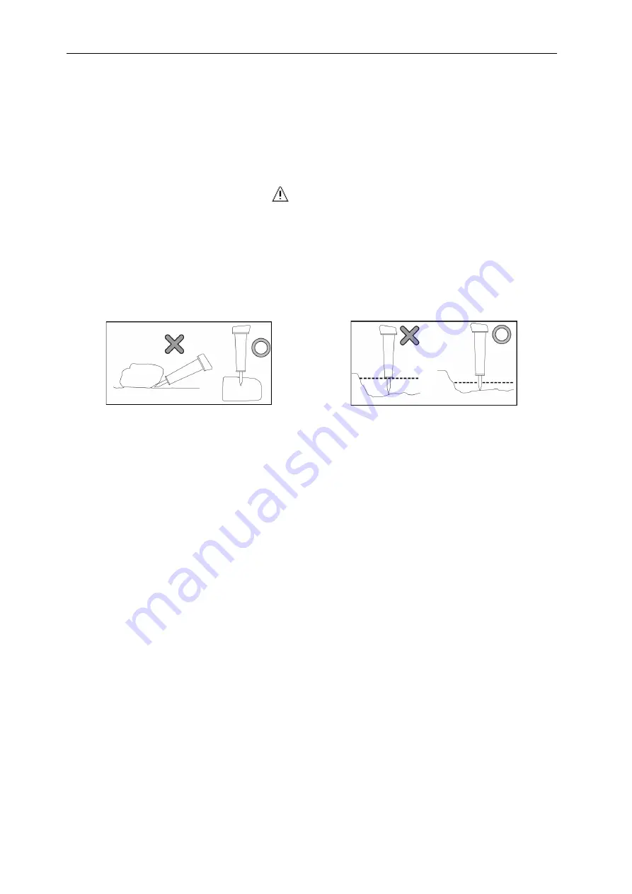
The hammer must be at 90° to the working surface.

In a submerged area, make sure that the water does not reach the body of the hammer.

Note

The hammer can only operate within the following temperature range:

[-5°C ~ +45°C]

To avoid damaging the structure of the hammer and minimize vibration, the operator must be

smooth when using the tool.Be sure to set the engine speed if you are using a hammer.

Once the work requiring the hammer is finished, set the hammer vertically with respect to the

ground and leave it in this position to facilitate drainage of condensation on the side of the
piston.

Tool change

IMPORTANT

Do the following operations with gloves and safety shoes.

Always use oils and greases recommended by YANMAR.

1. Park the machine preferably on a stable, flat and level surface.

2. Place the accessory at about 30 cm above the ground in horizontal position.

3. Stop the engine.

4. To remove the tool from the housing:

105

Summary of Contents for SV26

Page 1: ...USER OPERATION AND MAINTENANCE MANUAL SV26 MINI EXCAVATOR Original manual MUB17ENMA00101 16 01 2015 ...

Page 2: ...e to transform its perfomances beyond the original factory speci fications the warranty expires and the improvements on site under warranty are rejected The use of fuel beyond the specifications required or boosting the machines engines will cancel the warranty All the information illustrations and specifications contained in this manual are based on the lat est product information available on pu...

Page 3: ......

Page 4: ...SO 3744 NF ISO 6395 produced by CETIM centre technique des Industries Mécaniques 52 avenue Félix Louat BP 80067 60304 SENLIS Cedex FRANCE Net power output 17 6 kW 2400 rpm Measured sound pressure 92 7 dBA Guaranteed sound pressure 94 dBA Name and address of the person established in the European community authorized to compile the technical file and transmit it in whole or part to the public autho...

Page 5: ......

Page 6: ...N Note information about your YANMAR machine here Always use these references for everything to do with your YANMAR machine Model name Machine serial number Serial number of the engine Your YANMAR dealer Address Telephone ...

Page 7: ......

Page 8: ...her user do not forget to pass on the manual at the same time YANMAR provides its customers with products that conform to the regulations and industrial standards that apply in their respective countries If you are using a YANMAR machine that you have bought from a foreign company you should be aware that certain safety mechanisms may be missing from the machine Consult your dealer to find out whe...

Page 9: ......

Page 10: ... operator of this machine must be competent and trained in its use WARNING Never try to operate or repair the machine if you have not read and understood all the ap plicable warnings and usage instructions contained in this manual and on the safety signals on this machine Physical injury may be caused if the safety instructions are not respected WARNING Never modify the design of the machine or it...

Page 11: ...4 5 1 1 Indicator lights 14 5 1 2 Diesel gauge 16 5 1 3 Cooling fluid temperature indicator 16 5 1 4 Time counter 16 5 1 5 Navigation keys 17 5 1 6 Information and error icons 17 5 2 Switches 18 5 2 1 Start key 18 5 2 2 Headlight switch 19 5 2 3 Cigar lighter 19 5 2 4 Horn 20 5 2 5 Windscreen wiper switch and windscreen wiper 20 5 2 6 Ventilation switch 20 5 2 7 Interior lighting switch 21 5 2 8 B...

Page 12: ...ralized greasing system 46 7 18 Mechanical quick coupler 48 7 18 1 Mechanical quick coupler ARDEN EQUIPMENT 49 7 18 2 Mechanical quick coupler RETROMATIC MORIN 50 7 18 3 Mechanical quick coupler CSERI 51 7 19 Quick hydraulic attachment CSERI 52 7 19 1 Dismantling the accessory 53 7 19 2 Mounting the accessory 53 8 Covers 55 8 1 Bonnet 55 8 2 Cover B 56 8 3 Circuit breaker 56 B Operating instructio...

Page 13: ...2 3 6 Working on a slope 73 2 3 7 Working in an area covered with snow 73 2 3 8 Working on unstable ground 74 2 3 9 Working in a submerged area 74 2 3 10 Working in a muddy area 74 2 3 11 Working in an area with reduced visibility 75 2 4 Parking precautions 76 2 4 1 Parking location 76 2 4 2 Stopping the engine 76 2 5 Precautions for the accessories 77 2 6 Precautions for using optional accessorie...

Page 14: ...d hydraulic circuit 112 14 1 Description 112 14 1 1 3rd circuit selector 112 14 2 Mounting the accessory 113 14 3 Precautions for using the accessory 113 15 Transporting the machine 114 15 1 Loading unloading the machine 114 15 1 1 Precautions for loading unloading the machine 114 15 1 2 Procedure 114 15 2 Immobilising the machine on the truck 115 15 3 Tying down the machine 115 15 4 Slinging the ...

Page 15: ...2 6 1 1 Checking the machine before use 142 6 1 2 Checks after using the machine 142 6 1 3 Checking the commands 142 6 1 4 Checking the seat 142 6 1 5 Greasing points 143 6 1 6 Using the centralized greasing system 144 6 1 7 Cleaning the separator decanter 145 6 1 8 Purging the fuel tank 146 6 1 9 Checking the hydraulic hoses 145 6 1 10 Visual inspection of the fuel hoses 148 6 2 Maintenance every...

Page 16: ... E Technical data 163 1 Specifications 165 2 Working dimensions 166 3 Noise emitted by the machine 167 4 Vibrations emitted by the machine 168 F Lifting capacities 169 1 Lifting SV26 Cabin 171 2 Lifting SV26 Canopy 172 Appendices 173 A List of error codes displayed on the operator display station 174 B Control sheets to be photocopied 177 C Notes 183 D Lashing record 184 Index 185 ...

Page 17: ......

Page 18: ...on of the machine CHAPTERS COVERED IN THIS CHAPTER 1 APPLICATIONS AND REGULATIONS 2 IIDENTIFICATION PLATES 3 WARNING LABELS 4 IDENTIFICATION OF IMPORTANT PARTS 5 DESCRIPTION OF THE DRIVING POSITION 6 HEATING VALVE 7 OPTIONS 8 COVERS ...

Page 19: ...2 ...

Page 20: ...erning the driving permits Respect all applicable laws See your dealer for questions about usage permits 1 4 Lifting Using the machine as a hoist is subject to the Machinery Directive 2006 42 EC for members of the European Community and to the legislations specific to each country for states outside the EC YANMAR CONSTRUCTION EQUIPMENT EUROPE S A S declines all responsibility for any use of the ma...

Page 21: ...thout operator equipped with a standard bucket and tanks topped off 5 Weight of the machine with operator 75 kg 6 Serial number and engine power 7 Machine serial number 2 2 Engine serial number plate The engine s serial number plate is located on the top of the lifting arm lever cover and on the adhe sive label located inside the bonnet Never remove this plate for any reason 2 3 EPA information pl...

Page 22: ... and intervention request When you order spare parts or call for an inerven tion tell your dealer the model name the serial number of the machine and the serial number of the engine and the number of hours displayed on the time counter 1 Time counter ...

Page 23: ...see whether all the messages are in the correct location and are legible If an adhesive label is missing damaged or illegible replace it straight away In the same way if an adhesive label is on a part that has been replaced add a new adhesive label to the new part Contact your YANMAR dealer to obtain new adhesive labels The part code number is clear ly indicated on each label ...

Page 24: ...3 Warning labels 7 3 1 Location of the warning adhesive labels ...

Page 25: ...3 Warning labels 8 ...

Page 26: ...nual 2 1 5 Accessing the machine page 65 2 Usage precautions page 63 4 Do not remove the protective casings while the machine is running 2 2 9 Radiator ventilator page 135 5 Pressurised elements Do not unscrew while the liquid is hot 1 8 Avoid removing the caps when the temperatures are high page 61 6 Hot surfaces 4 3 Checking and topping up the engine oil level page 82 7 8 3 Circuit breaker page ...

Page 27: ...osite 6 2 1 Greasing the pin and rotation crown page 146 14 This sticker describes the operation of the machine controls and their location relative to the operator seat Options 5 3 Joysticks and pedals page 22 15 Tie down and slinging plans for the machine 15 Transporting the machine page 114 16 Filler holes for various reservoirs on the machine and track tension system 3 Recommended greases and ...

Page 28: ...een the bucket and the machine 10 2 Compatible accessories page 101 22 1 13 Cabin s emergency exit page 62 23 The maximum weight when in use in bucket mode or with accessories ensure machine dynamic stability in use It corresponds to the maxi mum weight allowed at the end of the empty arm 10 1 Machine stability when using with a bucket or an accessory page 99 Lifting capacities F Lifting capacitie...

Page 29: ...Left C Front D Rear 1 Blade 2 Boom cylinder 3 Bucket 4 Bucket pin 5 Bucket link 6 Arm 7 Bucket cylinder 8 Arm cylinder 9 Boom headlamp 10 Boom 11 Cabin 12 Sprocket wheel 13 Support roller 14 Track roller 15 Idle wheel 16 Track 17 Boom base 18 Boom rotation cylinder 19 Blade cylinder ...

Page 30: ...ft command lever 3 Armrest 4 Slide movement levers 5 Side movement pedals 6 Operator display station 7 Glove box 8 3rd hydraulic circuit control 9 Horn 10 Right command lever 11 Blade lever 12 Control panel 13 Start key 14 Throttle lever 15 Cup holder 16 Interior lighting switch for cab ...

Page 31: ...ing a light co mes on and the alarm sounds WARNING When an indicator light comes on and the alarm sounds during operation stop the engine immediately and follow the steps recommended in this manual 1 Indicator lights 2 Clock 3 Time counter 4 Diesel gauge 5 Cooling fluid temperature indicator 6 Menu change 7 Indication of functions 8 Keys F1 to F4 For the advanced features on the operator display s...

Page 32: ...ate the presence of information such as maintenance indications Press F4 to view the details d Hydraulic oil temperature gauge This indicator lights only at startup and it does not have any function on this machine e Travel speed indicator Increased speed This indicator shows that the 2nd gear is engaged f Battery charge warning alert If the battery is not correctly charged the warning light will ...

Page 33: ... If the temperature of this coolant reaches the limit 2 during working then slow the engine down and wait for it to return to normal When the engine is cold top up with cooling fluid following the procedure described in chapter 4 2 Checking and topping up the level of cool ing fluid page 81 5 1 4 Time counter 1 Time counter The time counter indicates the number of hours for which the machine has b...

Page 34: ...indicates on the basis of the machine s accumulated hours of use that the maintenance period for an maintenance object has been reached Required maintenance must be performed after referring to the maintenance section of this manual When the maintenance has been performed the accumulation of maintenance time must be reset from the maintenance interface 1 Periodic inspections and upkeeps page 129 E...

Page 35: ...r display station as well an error code stop the machine immediately and contact your dealer A List of error codes displayed on the operator display station page 174 5 2 Switches 1 Start key 2 Headlight switch 3 Horn 4 Windscreen wiper switch and windscreen wiper 5 Ventilation switch 6 Interior lighting switch 7 Boom rotation selection switch PTO 1 8 2nd gear switch 9 Cigar lighter 7 Options page ...

Page 36: ...ts and it will return itself to ON position 5 2 2 Headlight switch ON The headlights come on OFF The headlights switch off IMPORTANT Do not leave the headlights switched on when the engine is not running The battery will dis charge and the engine will be unable to start 5 2 3 Cigar lighter Push in the button It rises automatically when the re sistance is hot IMPORTANT If the cigar lighter does not...

Page 37: ... Do not press the washer command when the washer tank is empty as this may damage the pump Using windscreen wipers on a dry windscreen may damage the glass Only use the wind screen wipers when the windscreen is wet The windscreen wiper blade may freeze in cold weather Do not try to activate it if it is fro zen as this may damage the windscreen wiper motor 5 2 6 Ventilation switch Use this switch t...

Page 38: ... Boom rotation selection switch PTO 1 Press this button to select the knob mode of operation on the right joystick When the switch is positioned on boom rotation the alarm is triggered 1 P T O 1 2 Rotation of the boom 5 3 3 3rd hydraulic circuit control P T O 1 page 24 5 2 9 2nd gear switch 1 To switch to 2nd gear press the switch on the blade lever The 2nd gear indicator lights on the LCD monitor...

Page 39: ...tion of the driving position 22 5 3 Joysticks and pedals 1 Locking lever 2 Left command lever 3 Right command lever Rotation of the boom 4 Travel levers and pedals 5 Throttle lever 6 Blade lever 2nd gear switch ...

Page 40: ...on and travel can not be activated although the left and right joysticks can be manipulated WARNING Place the locking lever s in locked position as soon as you leave the seat WARNING The movement relationship between the command lever mechanism and the equipment mo vements thay produce are described in detail in this manual To avoid any accidents due to handling errors it is prohibited to modify t...

Page 41: ...ge 112 1 Proportional roller Dual action accessory tilt bucket auger etc operate only the proportional roller 5 3 4 Left command lever The left hand joystick is used to control the arm movements and the rotation of the upper part Handling the arm 1 Left command lever Rotation of the upper part 1 Left command lever When you release the lever it returns to neutral position and the respective movemen...

Page 42: ...the machine must familiarise themselves with the content of this manual before carrying out a task WARNING Before handling the travel levers check whether the machine is in normal or reverse posi tion The machine is in the normal position when the blade is on the same side as the work equipment If the machine is in the reverse position the displacement levers must be handled in re verse to move fo...

Page 43: ... to turn the machine To turn right do the same thing with the right travel lever To turn to the left with the machine stopped 1 Position the travel levers in the neutral position 2 Push the right travel lever to rotate for ward or pull the right travel lever to turn backwards To turn right do the same thing with the left travel lever To make a rotating turn of the machine to the left 1 Position th...

Page 44: ...ond gear 5 2 9 2nd gear switch page 21 WARNING The blade movement is not secured by the locking lever even when the latter is in the loc ked position Do not operate the blade lever when you are not using it 5 4 Power socket The intake located on the left under the seat works when the ignition key is in the ON position Appliances up to 12V 120W 10A may be connected 1 Lid 2 Power socket IMPORTANT Al...

Page 45: ...Location for the tools and user manual 5 6 1 Toolkit The space for the toolkit is underneath the dri ver s seat Pull the lever 1 to open the lid 2 Keep the toolkit in the compartment provided for the purpose 3 5 5 Driver s seat Adjust the seat position so that the driver can operate the controls easily and comfortably WARNING Do not adjust the seat position when you are working on the machine adju...

Page 46: ...ical system does not work when the key is on re place the faulty fuse with a fuse in good condition 6 3 1 Fuse replacement page 146 The general supply fuses are located beside the batte ry under the seat The fusebox is underneath the driver s seat a opening 1 General supply fuses 2 Delayed action fuses 5 6 2 User manual The location for the user manual is in the document holder below the ceiling P...

Page 47: ...s Options D 15A Windscreen wiper Windscreen washer E 20A Safety relay Anti theft mechanism Options Preheating relay Operator display station Enginestop solenoid Alternator Electric engine fuel supply pump Right command lever Left command lever Boom rotation relay PTO 1 F 5A Safety valves Options Cut off valve G 1A Radio Options H 20A Centralized greasing system Options Automatic engine idle Option...

Page 48: ... relay M 80A Starter Alternator N 80A Main circuit 5 8 Ash tray Pull the ash tray to open it 1 Close it again when it is not being used To empty and clean it press on the two ends and pull it towards you To put it back slide it into its housing keeping it flat A Ash tray WARNING Do not place any flammable products in the ash tray ...

Page 49: ...een 2 Lower windscreen 3 Side door WARNING Place the locking lever s in locked position to avoid any unplanned operation of the joys ticks when handling the windscreen 5 9 1 Cab side door 1 Exterior handle 2 Key 3 Interior handle a Opening and closing of the door From the exterior To open the door 1 Insert the key into the lock 2 Turn the key anti clockwise to unlock the door 3 Pull the exterior h...

Page 50: ...r engaging the cylindrical lock 1 To unlock the door 1 Pull the handle to disengage the cylindri cal lock 2 2 Close the door with the handle 5 9 2 Upper windscreen Opening of the upper part of the windscreen 1 Grasp the handles a and push the levers to the right and left of the window until you hear a click for them to unlock a Handle b Push 2 Remount the top part of the windscreen and drag it bac...

Page 51: ...ceiling to release the upper part of the windscreen 2 Slowly lower the windscreen holding the handles 5 9 3 Right hand cab window 1 Open the right hand cab window by sliding it in the direction indicated by the arrows 2 Tighten the pressure lock to hold the window in the position you want 3 To close the window loosen the pressure lock A Handle ...

Page 52: ... 5 10 Headlights WARNING The headlight becomes very hot when it is operating Never touch it with your bare hands before it has cooled down to avoid any risk of burning Boom headlamp Cab headlight Options Canopy type Options Tail light Options ...

Page 53: ...ion do the following 1 Heating valve 1 Perform the machine s parking operations 2 4 2 Stopping the engine page 76 2 Open the bonnet with the ignition key 3 Turn the valve in the locked position to stop the heating function 4 Close the engine bonnet Note To restore the heating function reverse the process ...

Page 54: ... to chapter 5 3 3 3rd hydraulic circuit control P T O 1 page 24 Adjustable proportional PTO Use the proportional roller to adapt the dual effect P T O rate The adjustable proportionality allows better P T O flow control by combining a knob with the proportional roller 1 Proportional roller 2 Knob 3 Position holding button To use the adjustable proportionality system 1 Operate the accessory with th...

Page 55: ...s the position holding button again to return the pressure to its starting level CAUTION Do not use the position holding with bucket tilting you would risk damaging the machi ne s hydraulic circuit 7 3 PTO line 2 Use the proportional roller on the left joystick to use the accessory mounted on the PTO s second line PTO 2 may be associated with a knob to make it an adjustable proportional PTO line P...

Page 56: ...hen the auto idle switch is ON and the machine controls are in neutral the engine speed is automatically reduced after 4 seconds If you use the machine controls the engine speed will automatically returns to the speed set by the engine speed knob ON Auto idler activated The indicator light is on OFF Auto idler deactivated The light is off Engine rate setting The throttle lever is replaced by a kno...

Page 57: ...bet ter stability and greater lifting capacities 1 Additional counterweights 7 6 Lifting Kit 1 Arm valve 2 Boom valve 3 Blade valve 4 Lifting Tables 5 Overload box 6 Lifting ring WARNING Do not perform lifting operations without the lifting equipment listed below being instal led on the machine 13 Load lifting page 111 ...

Page 58: ...oid the equipment falling to the ground if the hoses break 7 6 3 Overload box When the operator wishes to handle something it is imperative that the overload box switch is in the ON position to inform the operator of the tipping points depending on the load being handled and the position of the equipment An audible signal warns the operator that the load that he is handling is too heavy and could ...

Page 59: ...ating the machine Check it out before doing any load lifting 7 7 Movement alarm The machine can be fitted when this option is requested The travel alarm is composed of displacement sensors and a buzzer When the side movement levers are pushed or pulled the movement sensors are activated and the alarm sounds 7 8 Protection of cylinder The cylinders for the arm boom and bucket can be replaced with m...

Page 60: ...flash ing light 7 10 Keypad immobilizer The machine can be fitted when this option is requested The theft deterrent keypad consists of an immobilizer box and a keypad installed in the cockpit For more information consult the instructions supplied with the device 1 Once the user code has been programmed type A then the 4 digit code and press button V Note When the code is recognised the green light...

Page 61: ...the left will light up 2 Then turn the starter key within 60 seconds 7 12 Anti starter with key The machine can be fitted when this option is requested The immobilizer key consists of an immobilizer box and a key reader installed in the cockpit For more information consult the instructions supplied with the device To start the engine insert the MED elec tronic key into its housing remove it and st...

Page 62: ...use of mobile phones is prohibited hospitals airports mining ope ration area The ME401 2 unit can be coupled on your machine to an anti theft system with a hydraulic lock or immobilizer 7 14 Bio oil WARNING When working on your hydraulic system contact your dealer Standard bio oil The machine can operate with biodegradable hydraulic oil Panolin bio oil The machine can operate with biodegradable hy...

Page 63: ...he adapter into the receiver A slight click indicates that the connection is success ful The ball is released from the adapter groove located on the receiver 2 Turn the adapter on the receiver to secure the connection Note Before each use clean the receiver surfaces disconnecting To disconnect turn the adapter to align the ball with the groove located on the receiver and slide the adapter backward...

Page 64: ... and fluids page 137 CAUTION Do not plug the hole at the top of the tank in order not to block the filling DANGER In case of over filling the tank can burst and cause physical injuries A Tank B Filling connector MAX Filling limit 7 17 Centralized greasing system The centralised lubrication automates the greasing of the swivel pins on your machine It co mes with a timer allowing adjusting the lubri...

Page 65: ...recommended in the parts catalogue IMPORTANT Before using an accessory requiring hydraulic power check the pressure compatibility from the machine specifications chart 1 Specifications page 165 WARNING Before mounting a bucket or an accessory on your machine make sure that the bucket or accessory is compatible with the capabilities of your machine 10 2 Compatible accessories page 101 the bucket or...

Page 66: ... locked position 7 18 1 Mechanical quick coupler ARDEN EQUIPMENT Quick coupler structure The quick change system is composed of A Fastening hooks B Locking pins C Locking screw Dismantling the accessory 1 Park the machine preferably on a stable flat and level surface 2 Place the accessory at about 5 cm above the ground 3 Be equipped with the wrench supplied with the accessory and insert it into th...

Page 67: ...ccessory 5 Remove the key and store it 6 Manoeuvre the arm to disengage the tool s quick coupler Mounting the accessory 1 Place the accessory on a stable flat surface 2 Clean all the parts 3 Place the arm equipped with the quick cou pler on the accessory to engage the accessory hooks on the bucket or accessory pin 4 Rotate the quick coupler by slowly lower ing the boom to fully engage the quick co...

Page 68: ...pletely free the quick coupler from the bucket or accessory Mounting the accessory 1 Place the accessory on a stable flat surface 2 Clean all the parts Note Make sure the locking pins are retracted into the quick coupler If the pins are in the extended position a Be equipped with the wrench supplied with the accessory and insert it into the quick coupler hole b Turn the key 1 to disengage the buck...

Page 69: ...installed on the machine 1 Quick hydraulic attachment 2 Quick attachment control unit Quick hydraulic attachment When the locking pins retract a indicator pin is visible in the quick coupler When the locking pins are removed the indicator pin retracts and is no longer visible A Locking pins B Fastening hooks C Indicator pin 1 Power supply contact 2 Lock switch 3 Light Quick coupler unlocked red 4 ...

Page 70: ... to disengage the accessory hooks on the bucket pin or accessory 6 Move the quick attachment away from the accessory 7 Turn the switch 1 to OFF The light goes off and the alarm stops 7 19 2 Mounting the accessory 1 Turn the switch 1 to ON The contactor switch indicator lights and the alarm sounds WARNING If the warning light does not come on or if the alarm does not sound stop the current ope rati...

Page 71: ...ngage on the bucket or accessory to lock it The green light comes on The control rod is not visible DANGER Make sure that the control rod is retracted into the quick coupler and is no longer visible Otherwise check the condition of the interface between the quick coupler and the accesso ry cleanliness shock It is forbidden to operate the bucket or the accessory if the control rod is still visible ...

Page 72: ...f of the va rious levels should be done when the engine is stopped and the temperatures are brought back down Opening the cover 1 Insert the starter key into the lock 2 Turn the key anti clockwise 3 Pull the lever to unlock the safety mechanism The cover opens 1 Exterior handle 2 Key A Pull Closing the cover 1 Close the cover 2 Press on it until you hear a click 3 Turn the key clockwise to activat...

Page 73: ...2 Turn the key anti clockwise 3 Pull the lever to unlock the safety mecha nism The cover opens 4 Lock the cover using the rod Closing the cover 1 Lift the cover slightly and press the rod to release it 2 Close the cover 1 3 Turn the key clockwise to activate the lock 2 8 3 Circuit breaker This switch is used to disconnect the battery directly 1 Circuit breaker ...

Page 74: ...FTER START UP 6 CHECKS AFTER USE 7 OPERATOR LCD DISPLAY STATION INTERFACES 8 USING THE MACHINE IN COLD WEATHER 9 RUBBER TRACKS 10 HANDLING THE BUCKET 11 HANDLING OF ACCESSORIES 12 ACCESSORY CHANGE BY DIRECT COUPLING 13 LOAD LIFTING 14 IMPLEMENTING THE 3RD HYDRAULIC CIRCUIT 15 TRANSPORTING THE MACHINE 16 DETECTING ANOMALIES 17 IF THE BATTERY IS DISCHARGED 18 TOWING THE MACHINE ...

Page 75: ...58 ...

Page 76: ...ronment and thus the machine must not be used in such environments 1 2 Put the safety mechanisms in place Make sure that all covers and all housings are properly installed in their respective positions If any of them are damaged repair them immediately The use of safety mechanisms such as locking lever s must be mastered and understood by the machine s operator Operating the locking lever s 5 3 1 ...

Page 77: ...umes The silencer and radiator release hot air and exhaust fumes at high temperatures If the hot air directly reaches a plant it alters its state and may cause its death Protect plants from hot air and exhaust fumes with a protective plate when you are working near a hedge or plants 1 7 Keep fuel and oil away from sparks Leaving flames near fuel oil hydraulic oil or anti freeze solutions which are...

Page 78: ...n Specify the action to be carried out in the event of a fire or accident Indicate the person to be contacted in the event of an emergency and leave the emergency call number near your telephone A location to install an extinguisher is provided inside the machine s cab 1 10 Avoid any unauthorised modifications Any unauthorised modification to the design or use of unauthorised accessories may cause...

Page 79: ...accessories 12 Accessory change by direct coupling page 107 Only use accessories authorised by YANMAR The use of unauthorised accessories risks af fectingnot only the safety of the machine but also its operation or life span The use of unauthorised equipment will contravene the terms of the YANMAR warranty and cancel it 1 12 Warning concerning the cab windows If by accident a cab window is broken ...

Page 80: ... the field and the ground and decide on the best way to work When working on the street make sure the worksite is secure If you have to use the machine under specific conditions water snow etc 2 3 7 Working in an area covered with snow page 73 2 1 2 Clean the machine Cleaning Wood chips dead leaves detritus and other flammable materials around the engine may catch fire Clean these materials from t...

Page 81: ...e hands until it has cooled down to avoid any risk of burning 2 1 3 Check the safety structures The standard machine is equipped with a Falling Objects Protection Structure FOPS on the machine s roof The protection structures mounted on the machine comply with the recommendations of ISO 12117 2 of 2008 ROPS and 10262 of 2000 FOPS For the specifications of these structures refer to the table below ...

Page 82: ... out of the machine when it is op erating as this may cause physical injuries When you enter and leave the machine face the machine and use the handles and the top of the track Use the contact points indicated by arrows in the il lustration opposite to climb onto and descend from the machine Do not use the command levers as handles Always maintain three points of contact If the handles or the trac...

Page 83: ...d run the machine only from the operator seat A signaller must be provided when the working site is dangerous or has poor visibility Keep all other people away from the working site or movement route of the machine Keep any other persons out of the danger zone repre sented by the equipment s operating radius Equipment operating range 5m Alert people nearby using the horn or any other si gnal befor...

Page 84: ... When driving the machine on a slope keep the buck et between 20 and 30 cm above the ground to be able to lower it to the ground and stop the machine in the event of an emergency WARNING Never travel across a slope of 20 or more as the machine may tip over Never turn the machine on a slope and do not move it across a slope Descend to flat ground and then turn Note For the maximum acceptable slope ...

Page 85: ...b a slope with the travel motors alone plant the bucket into the ground retract the arm and move forward Repeat this operation as many times as necessary If the engine stops If the engine stops when climbing an incline position the travel levers in the neutral position and lift the locking lever then stop the machine and restart the engine If the machine does not start pull the locking lever and c...

Page 86: ...pt where unavoidable Do not use the side movement force to dig the ground with the bucket s teeth in contact with the ground This may apply excessive force to the rear of the machine and shorten its life span a Do not use the hydraulic cylinder to the end of its run a play This may apply excessive force to the cylinder s stop piece and may reduce the equipment s life span Maintain safe room for ma...

Page 87: ...lowering force to dig the ground When excavating a hard rock keep the ma chine s tracks flat on the ground Note It is also recommended to break hard rock into several pieces using other means to prevent damage to the machine Be careful when pulling the equipment out When you retract the equipment for side move ment and transport make sure that the bucket and blade do not come into contact ...

Page 88: ...does not come into contact with the boom cylinder Place the blade at the back if it is not in use Do not lift loads without a suitable fastening device it is strictly forbidden to wrap a sling around your machine s accessory or suspend it to a bucket tooth 13 Load lifting page 111 2 3 2 Dangerous tasks Digging from the top is dangerous as there is a risk of rock falls or landslides Digging from th...

Page 89: ... of the wires on the work site contact the electricity production com pany concerned Voltage V Minimum safety distance m Transformer 100 200 2 6600 2 Transmission line 22000 3 66000 4 154000 5 275000 7 2 3 4 Working near obstacles When moving in a tunnel under a bridge or when you are working in an area near tall obsta cels drive the machine carefully to avoid knocking the boom the arm or the acce...

Page 90: ...tating the upper structure or when ro tating equipment on a slope Do not pivot the upper structure with a load in the bucket If the rotation cannot be avoided provide a bank to keep the machine as horizontal as possible Then turn the upper structure Note For the maximum acceptable slope 1 Specifications page 165 2 3 7 Working in an area covered with snow Ground covered with snow and icy roads are ...

Page 91: ... with a high risk of rock fall wear a helmet and remain under the canopy or in the cab 2 3 9 Working in a submerged area Before you use the machine in a submerged area examine the condition of the ground and the depth and flow of the water The maximum depth of water in which the ma chine may be used is located up to the centre of the carrying roll IMPORTANT When you come out of the water if the ma...

Page 92: ...k 1 Place a log or piece of wood under the tracks 2 Push the bucket into the firm ground 3 Retract the arm as if to dig and move for ward with the side movement levers to get out of the mud 2 3 11 Working in an area with reduced visibility When working in a dimly lit area switch on the lights and front headlights and provide addi tional lighting if necessary Stop all work when fog snow or rain hin...

Page 93: ... ground 5 Pull the locking levers back 1 Locking 2 Locking lever 3 Left hand side 6 Turn the key to OFF position to switch off the engine and disconnect the electrical circuit 7 Remove the key from the ignition WARNING Do not touch the command levers before switching off the engine or else the equipment or the machine may move suddenly and cause a serious accident 2 4 Parking precautions 2 4 1 Par...

Page 94: ...he machine the inertia of the upper structure will increase and continue to rotate over a long distance once the rotation lever has been released This may give the operator a false impression of the distance to be respected between the piv oting accessory and a nearby object and may strike the accessory against the object To avoid this type of accident stop the rotation as soon as possible Because...

Page 95: ...mmable Keep the battery away from all flames and sparks If you accidentally swallow any of the battery s electrolyte drink a large quantity of water milk or fresh eggs and consult a doctor immediately Before inspecting or handling the battery switch off the engine and turn the starter switch to OFF Make sure that you do not cause a short circuit by touching the battery terminals with a tool If a t...

Page 96: ...ore despatch Otherwise there is a risk that its performance will be affected and its life span shortened When running in the machine make sure to Preheat the engine by running it on idle for 5 minutes after starting it Do not run the machine with a heavy load or at a high speed Do not start accelerate or stop the engine suddenly Do not change direction too suddenly Note Observe these precautions t...

Page 97: ...the dust and combustible materials dead leaves chips on areas where heat devel ops around the engine the battery and the radiator 3 Check that there are no oil leaks from the engine or water leaks from the cooling system 4 Check that there are no oil leaks from the hydraulic system the hydraulic oil tank the pipes and seals 5 Check that there are no traces of grease or leaks from the hydraulic pip...

Page 98: ...cedure 1 Place the machine on flat ground 2 Stop the engine 3 Wait until the engine and the radiator have cooled down 4 Open the bonnet with the ignition key 5 Check that the level of fluid in the tank is between the min and max markers A expansion flask 1 maxi 2 mini If the level is below the min marker 1 Take the cap off the tank 2 Top up to the maximum marker 3 Close the tank again 4 Close the ...

Page 99: ...g hole and top up to marker H F Filler hole If the oil level is above marker H remove the excess quantity of oil via the drainage cap P then check the level again Note Do not pour the excess engine oil onto the ground or the road Once the engine oil is at the appropriate level close the bonnet again Select the oil according to the temperature If you start the engine at temperatures below 0 C use a...

Page 100: ...ermine the fuel level by looking at the fuel gauge on the dashboard 3 Set the starter key to OFF position 4 Top up if the level is low a Open cover B using the starter key b Take the cap off the tank c Top up through the filler hole keeping an eye on the gauge located on the tank 1 Cap Only use the recommended diesel ISO 8217 DMX EN 590 96 Minimum cetane index 45 Temperatures C Quantity prescribed...

Page 101: ...achine 84 1 Event 5 Close the tank again 6 Close cover B Note If the cap vent holes are plugged the pressure in the reservoir may vary and the fuel supply will be faulty To avoid this happening clean these vents air holes regularly ...

Page 102: ...marker on the oil gauge scale oil temperature 50 to 80 C 4 If the oil level is below the minimum marker top up as follows a Open the rear bonnet b Open the hydraulic oil tank opening cap c Top up through the filler hole keeping an eye on the gauge located on the tank 5 Close the tank again 6 Close the engine bonnet 1 Upper limit 3 Filler hole IMPORTANT Do not top the hydraulic oil over the upper l...

Page 103: ...4 Checks before starting the machine 86 Replacing the hydraulic oil The hydraulic oil must be replaced every 1000 hours Contact your dealer ...

Page 104: ... hot After the engine starts do not use the machine immediately but respect the following procedure 1 Run the engine on idle and check that the engine oil pressure alarm light is off 2 Check that the gauges and the screen correspond to the following statuses 1 Diesel gauge normal 2 Cooling fluid temperature indicator normal 3 Time counter normal 4 Hydraulic oil temperature gauge off 5 Battery char...

Page 105: ...ccessory make sure it does not hit the ground or the machine IMPORTANT Check that there is no abnormal noise in the hydraulic circuit 6 Check the colour of the exhaust gas the noise and the vibrations of the machine 7 Raise the locking lever to ensure that no handling of the equipment and no rotation of the upper structure is possible with the joysticks 8 Unlock the locking lever and activate the ...

Page 106: ...Check whether the radiator vents are clogged Clean or replace the fuel filter cartridge regularly Clean the electrical equipment particularly the starter and the alternator to avoid any dust deposits If the machine is used in mud snow or sand Clean the machine Check there are no cracks or damage Check that no nuts or screws are missing Apply grease to all equipment axes that have been submerged in...

Page 107: ...nfirm the selection by pressing F4 7 1 Indication of functions This section of the menu indicates the functions of buttons F1 to F4 Return to previous menu Reset the selected value Move the cursor over the object to the left of the one selected Displays the details of an information notice maintenance notice for example Move the cursor over the object to the right of the one selected Stop the buzz...

Page 108: ... 1 Indicator lights page 14 7 3 Maintenance interface 1 Displays the maintenance interval screen 2 Displays the maintenance history screen 1 Maintenance object icon 2 Maintenance object name 3 Time accumulated since the previous maintenance 4 Maintenance interval This interface allows you to check the maintenance periods and cumulative elapsed time since the last maintenance for each main tenance ...

Page 109: ...shown in the table below Language Changes the language used by the various interfaces Date and time setting If the battery in the machine is removed the date and time settings will be reset Sound parameter Adjusts the monitor to emit a confirmation sound when a button is pres sed The buzzer sounds when the settings are changed or when a malfunc tion is detected can not be removed Brightness settin...

Page 110: ... 2 1 Precautions before starting the engine page 63 1 Pull the acceleration lever back to full gas position B Throttle lever 2 Turn the key to the ON position a Keep the key in the ON position to warm up the engine until the warm up icon no longer appears on the screen b When the glow plug icon no longer appears on the screen turn the key to the START position to start the engine c Release the key...

Page 111: ...the machine on firm dry ground or place boards on the ground and park the machine on these boards to avoid the tracks freezing on the ground 4 Drain the water built up in the fuel system by turning the evacuation tap to avoid and freezing 5 Cover the battery or place it in a warm place and reinstall it on the machine the next morning 8 4 When cold weather is over When the exterior temperature incr...

Page 112: ...e properties of the rubber tracks and comply with the handling and operating precautions for these tracks to extend their life span and get the most out of them 9 3 Rubber track warranty The rubber tracks are not guaranteed for repair and replacement if they are damaged follow ing careless use by the user lack of check of the track tension or incorrect maintenance use of the tracks on surfaces or ...

Page 113: ...that become oily once crushed soya wheat grains compressed colza oil yeast etc After use clean the machine fully with water We do not recommend that you use the machine to handle materials such as salt ammonium sulphate potassium chloride potassium sulphate or super lime biphosphate Transporting these materials risks damage the metals adhesion After use clean the machine fully with water Avoid the...

Page 114: ... 1 Track 2 Tightener roller When you carry out side movement in re verse there is another spacing between the ten sion roller and the track 3 Idle wheel when the machine is moving although the tracks have been blocked to the side by an obstacle when the idler pulley and the rollers are not aligned with respect to the tracks A Chassis side B Rubber track side when you are reversing under these cond...

Page 115: ...9 Rubber tracks 98 9 6 Track replacement 6 4 2 Track replacement page 149 ...

Page 116: ... operator before using the machine for excava tion levelling operations or in working conditions with the accessories Depending on the machine configuration arm length presence of a counterweight and working conditions the operator must make sure that The equipment and accessories selection is made according to the nature of the task to be car ried out and according to the machine s stability limi...

Page 117: ...on Weight handled Weight of equipped quick coupler Weight of the accessory hammer empty bucket Bucket load capacity x material density This operation is reminded by a sticker affixed in the cab interior and visible from the driver s compartment Compare the result with the maximum weight under condition of use with bucket shovel or with accessories Weight of quick coupler and accessories hammer emp...

Page 118: ...th a full bucket forming a dome in ac cordance with ISO standard 7451 For particular operations or with materials of different densi ties partial bucket filling due to fluid products such as mud larger buckets may be used In this case it is the responsibility of the user to ensure that the machine stability limit is not exceeded The machine could tip over which could cause serious physical injurie...

Page 119: ...g bucket R13 550 CM1 1000 Hydraulic hammer DMS 165 Mechanical wedge Arden equipement Quick attachment QA 05A Bucket Retro bucket R05G31 060 Ditching bucket C05R08 120 Swivel ditching bucket C05I04 120 Loading bucket Quick attachment QA 11M Bucket Retro bucket R10G11 070 Ditching bucket C10R08 120 Swivel ditching bucket C11I04 120 Loading bucket Hydraulic hammer DMS 165 Mechanical wedge CSERI Quick...

Page 120: ...nd the angle between the arm cylinder and the arm is 90 For maximum effectiveness handle the arm within the range illustrated opposite 45 forward and 30 back Do not move the equipment to the end of the cylinder run To dig at a level above the machine install the buck et in the reverse position 12 2 1 Loading bucket page 109 10 1 Machine stability when using with a bucket or an accessory page 99 10...

Page 121: ...crease effectiveness position the skip truck at a location where the operator may view it and where the machine s rotation angle is minimised Load the earth from the back of the truck to facilitate loading and maximise the quantity of earth loaded ...

Page 122: ...ation the operator must be smooth when using the tool Be sure to set the engine speed if you are using a hammer Once the work requiring the hammer is finished set the hammer vertically with respect to the ground and leave it in this position to facilitate drainage of condensation on the side of the piston Tool change IMPORTANT Do the following operations with gloves and safety shoes Always use oil...

Page 123: ...nd turn the tool in order to position it parallel to the pin housing 8 Use a lever to press the pin stop and make it fit into place 9 Insert the pin until the pin stop returns to its position Note There are different forms of tools that can equip the hammer Contact your dealer If the hammer is inactive for a long period you must Pull out the tool and after pushing the piston as high as possible us...

Page 124: ...ce the accessory at about 5 cm above the ground 3 Stop the engine 4 Clean all the parts 5 Remove the swivel pin from the A bore and the swivel pin from the B bore IMPORTANT Protect the various elements from dirt and dust Take care not to damage seals on each bushing side Verify the good state of o rings Replace them if they are damaged 107 ...

Page 125: ...ccessories page 101 the bucket or accessory mounting operation is performed on a level and stable ground the bucket or accessory is properly positioned to be installed on the machine 1 Clean and lubricate the bores 2 Put the o rings in place 3 Align the arm bore with the bore A Add shims to compensate for play if necessary 4 Insert the swivel pin into the bore A 5 Align the pin bore with the bore ...

Page 126: ...s remove the plugs from the hoses on the machine and drain the oil accumulated in the hoses Always drain the machine s oil into a safe container and never directly onto the ground 3 Connect ports A and P then ports B and T with hydraulic hoses 12 2 1 Loading bucket IMPORTANT Protect the various elements from dirt and dust Take care not to damage seals on each bushing side 1 Arm 2 Bucket link 1 Cle...

Page 127: ...the equipment and align the arm bore with the bucket B bore holding the bucket about 5 cm of the ground Add shims to compensate for play if necessary 6 Insert the swivel pin into bore B 7 Put the bolts in place on axes A and B 8 Grease the hinged parts ...

Page 128: ...limits during the lifting operation 3 Install a device that can oppose the accidental release of the load on the machine s lifting ring with latch hook shackle eye and whose WLL2 is equal to or greater than the load to be lifted 4 Attach the load to be handled with the lifting accessory 5 Pass the lifting accessory in the lifting device and lock the device 6 Turn the overload housing switch to ON ...

Page 129: ...cuit control CAUTION Do not operate the controls of the 3rd circuit if there are no installed accessories 14 1 1 3rd circuit selector Remove the rubber cap to use the 3rd circuit valve and select the single or double action mode A 3rd circuit dual effect B 3rd circuit single effect with direct tank return ...

Page 130: ... hydraulic tool s hoses Hydraulic oil rate at nominal engine speed 1 Specifications page 165 14 3 Precautions for using the accessory Follow the procedures described in the user manual provided by the accessory s manufacturer Hydraulic hammer single action accessory Set the return pipe selector valve to the position for a single action accessory The hammer works when the proportional roller is ope...

Page 131: ...y do not become detached Clean grease oil and any other slippery deposits from the ramps and remove the mud from the tracks to avoid the machine sliding sideways on the plates Do not load or unload the machine if the ramps are slippery due to rain snow or frost Load or unload the machine at reduced speed Never change the direction of travel on the ramps If you need to change your path take the ram...

Page 132: ... 3 Turn the key to OFF position to switch off the engine and disconnect the electrical circuit Remove the key from the ignition 4 Lock the control levers with the locking lever 1 Locking 2 Locking lever 3 Left hand side Note The hydraulic brake locks the rotation motor 15 3 Tying down the machine WARNING Do not perform the tie down if a person stands on the machine or on an accessory WARNING Use a...

Page 133: ...rd page 184 3 Check the location and condition of the machine tie down points 4 Tie down the machine at the points provided for that purpose and that are indicated on the machine YANMAR CONSTRUCTION EQUIPMENT EUROPE recommends securing the ma chine according to the diagonal direct tie down method respecting the angles shown below 4 Working Load Limit WLL Angle Value in degrees α 20 60 β 10 60 3 Wa...

Page 134: ...e weight of the machine and that complies with current standards If you do not lift the machine as shown it will be out of balance Do not pivot the machine when it has been raised Never walk under or beside a suspended machine 1 Pivot the upper structure so that the blade is behind the operator s seat 2 Lift the blade to the maximum limit 3 Place the equipment in the longitudinal axis of the machi...

Page 135: ...oles at the front 1 point and the rear 2 points 2 Load lifting accessories carefully 3 Gently suspend the machine and wait until it stabil ises before continuing to lift it Length m W L L 5 t C 1 5 m 2 D 3 m x 2 2 Note Use only shackles having a WLL5 equal or greater than 2t 5 Working Load Limit WLL ...

Page 136: ...hermal shock for the side movement motor If during cold weather the hydraulic oil temperature rises to over 60 C in relation to the exterior temperature during an unloading operation without movement after the engine starts the machine may not pivot because of a thermal shock This is not a fault The rotation cylinder extends during excavation The rotation cylinder may extend in certain situations ...

Page 137: ...ectric circuit The starter works correctly but the engine does not start Lack of fuel Top up the fuel tank Air in the fuel circuit Repair the air leak Evacuate the air from the fuel circuit Defective fuel injection pump or in jector performance altered Replace the pump or the injector Inadequate compression Check and repair Blown fuse Replace the fuse Stop solenoid damaged Broken filament Check an...

Page 138: ...um engine speed does not provide enough power to the lights Defective electric circuit Check the play and the proper con nection of the terminals Repair if necessary Defective alternator or regulator Check and repair When the engine is runnign the lamp is very bright and burns out frequently Defective regulator Replace the regulator Battery leak Defective battery Replace the battery The starter sp...

Page 139: ...ot rotate smoothly The rotation brake is not unlocked Unlock the rotation locking lever Insufficient quantity of grease Check and lubricate Defective rotation brake valve Check and repair Defective rotation motor Check and repair The hydraulic oil temperature is too high Insufficient quantity of hydraulic oil Fill the hydraulic oil to the required level Overload Reduce the load The machine does no...

Page 140: ...ative terminal mass If a tool comes into contact with the machine s positive terminal there is a risk of sparks Do not connect the connection cables to the terminals in reverse polarity For example never connect the negative terminal on one machine to the positive terminal on the other machine To connect start with the positive terminal 1 To disconnect start with the negative terminal 1 The capaci...

Page 141: ... and increase the engine speed to maximum 3 Turn the starter switch of the machine that has broken down to START to start the engine If the engine does not start wait at least two minutes before trying again Do not stop the engine on the repair machine and keep the engine speed at full rate 17 4 Disconnecting the starter cables After starting the engine on the machine that has broken down disconne...

Page 142: ...5 C stop the operation Stop the charging operation as soon as the battery is charged If you continue the following faults may occur battery overload reduction in the battery electrolyte battery failure Do not connect the connection cables to the terminals in reverse polarity For example never connect the negative terminal on one machine to the positive terminal on the other machine A polarity reve...

Page 143: ...hine gets stuck in the mud and cannot get out on its own or when it is towing a heavy object attach the sling as shown opposite 1 Shackles 2 Slings Minimum capacities of the coupling devices to use W L L 7 t Shackles 5 Slings 5 When towing a machine with another machine use a metal cable that is powerful enough for the machine s weight Never tow the machine on a slope Never use a deformed or damag...

Page 144: ...ERED IN THIS CHAPTER 1 PERIODIC INSPECTIONS AND UPKEEPS 2 MAINTENANCE PRECAUTIONS 3 RECOMMENDED GREASES AND FLUIDS 4 FIRST MAINTENANCE 5 LIST OF PERIODIC INSPECTIONS AND MAINTENANCE OPERATIONS 6 MAINTENANCE BY THE OPERATOR 7 MAINTENANCE BY THE DEALER ...

Page 145: ...128 ...

Page 146: ...e Hydraulic oil Hydraulic circuit Aspiration filter Hydraulic oil return filter 1st time Operation of the accumulator Greasing Greasing points Rotation pin and crown Chassis Bearing rollers and bearings idler wheels Track tension Electrical equipment Headlights horn travel alarm Dashboard and indicators System state Engine Water separator GO filter Air filter dusty atmosphere every 250 h Engine oi...

Page 147: ...eriodic inspections and upkeeps 130 Scheduled maintenance points of the machine lubrication filters Hydraulic oil Engine oil Hydraulic oil return filter Travel gears Greasing points Air filter Fuel filter ...

Page 148: ...peration remove residual pressure in the hydraulic circuit 1 Perform the machine s parking operations 2 4 2 Stopping the engine page 76 2 Turn the key to the OFF position to stop the machine s engine then turn it to the ON position Note The locking lever must be lowered 3 Handle the following controls several times to remove the residual pressure Left command lever Arm Rotation of the upper part R...

Page 149: ...the filler cap the vent hole and oil level glass gauge and prevent dust from mixing there Spots of oil or grease or dispersed part fragments are dangerous and may cause slipping Any water that gets into the electrical system may cause it to malfunction leading to defec tive operation of the machine This also risks causing short circuits that may cause a fire or elec tric shock Do not spray any vap...

Page 150: ...ed in the fol lowing chapters IMPORTANT Do not mix different types of oils If you need to top up the oil with a different make or type from the oil left in the tank remove the remaining oil completely 2 2 2 Tools Use tools that are adapted to the planned task The use of damaged worn or inappropriate tools is very dangerous and there is a risk that the machine will be damaged 2 2 3 Parts Use YANMAR...

Page 151: ...y out any maintenance or repairs under the machine place the accessory on the ground or in its lowest position Perform the machine s parking operations 2 4 2 Stopping the engine page 76 Before performing any maintenance operation remove residual pressure in the hy draulic circuit 2 1 2 Removing the residual pressure page 131 DANGER Park the machine on flat firm ground If the machine is not stable ...

Page 152: ...ire 2 2 9 Radiator ventilator WARNING Never touch the moving radiator ventilator or the ventilator belt with an object as this may cause seri ous physical injuries 2 2 10 Soldering If you need to solder respect the following points Disconnect the battery cabling negative terminal then positive terminal Disconnect the operator display station before performing a welding operation Ground the machine...

Page 153: ...ocessing Always drain the machine s oil into a safe container and never directly onto the ground When you get rid of toxic waste such as fuel oil cooling water solvents filters and used batteries respect the regulations that apply to this subject ...

Page 154: ...types of oils If you need to top up the oil with a different make or type from the oil left in the tank remove the remaining oil completely Components Fluid Temperatures C Quantity prescribed L 20 10 0 10 20 30 Thermal engine Engine oil SAE 10W CD 3 7 0 4 Oil filter SAE 10W 30CD SAE 15W 40CD Travel gears Box oil SAE 90 GL 4 0 5 by reducer Hydraulic circuit Hydraulic oil ISO VG46 25 2 in the tank 4...

Page 155: ... oil filter element replaced Replace the side movement reducer oil Greasing the pin and rotation crown Replace the hydraulic fluid return filter element Contact your dealer 4 2 After the first 250hours of service Fuel filter Replacement Contact your dealer 1 Periodic inspections and upkeeps page 129 ...

Page 156: ...re frequencies for examplen the operations to be carried out every 50 hours must be carried out at 50h 100h 150h 200h etc Certain intervals may vary if a hydraulic hammer is used Refer to the corresponding notes 1 2 X Y Note If a hydraulic hammer is used the re turn filter must be replaced after 100 or 150 hours of service for a new machine then according to the diagram opposite The hydraulic oil ...

Page 157: ...Checking and topping up the fuel level page 83 Engine oil 4 3 Checking and topping up the engine oil level page 82 Cooling fluid 4 2 Checking and topping up the level of cooling fluid page 81 Tracks 6 4 Rubber track maintenance page 147 Radiator vents Cleaning Alternator belt Tension check Decanter separator 6 1 7 Cleaning the separator decanter page 144 Operation of the accumulator Check Electric...

Page 158: ...or belt Replacement Cooling fluid Replacement Intake and exhaust valves Play adjustment Cylinder head block Bolt re tightening Fuel pump Check Bearing rollers and bearings idler wheels Greasing Heating Verification and adjustment Every 2000h Injectors and injection pressure Inspection and calilbration Fuel hose coolant hose Verification and replacement Intake and exhaust valves Running in Fuel pum...

Page 159: ... detect leaks sprays of hot oil Consult a doctor immediately if you are hit with any oil Also check that the time counter the headlights the alarm and the lights are working correctly If an element is not working or you think it is defective shut down the machine s engine im mediately and contact your dealer 6 1 2 Checks after using the machine After each use several checks must be carried out acc...

Page 160: ...fore using the machine or after use in the rain on soft ground or in muddy water Proceed as follows 1 Lower the bucket and the blade to the ground 2 Stop the engine 3 Clean the greasing connectors indicated by the arrows on the figures 4 Grease them with a grease pump 5 Wipe off the excess grease with a cloth or equivalent ...

Page 161: ... Once the lubrication is carried out the lubrication cycle restarts at zero 1 2 3 4 5 6 7 6 1 6 Using the centralized greasing system The timer is triggered at machine startup and stops at the machine s complete shutdown When the ignition switch is turned off the elapsed time before the next lubrication is saved and the timer restarts with this value when the machine is restarted To refill the cen...

Page 162: ...ooled down enough A diesel leak or spray onto a red hot element may cause a fire 1 Open the rear bonnet 2 Place a container under the separator 3 Close the purge tap B Decanter separator 4 Loosen the bowl tightening ring 1 Tightening ring 2 Closed 3 Open 4 Loosen 5 Tighten 6 Element 7 Ring 5 Remove the bowl 6 Empty into the container Make sure you do not lose the red floater 7 Remove the element a...

Page 163: ...ween the two tracks 2 Loosen the screws and rotate the bottom cover 3 Place a container to catch the fuel residue under the drainage tap 4 Remove the drainage cap to purge the water and dirt left in the tank 5 Once clean fuel starts to come out reinstall the drain plug and tighten to the right torque Maximum torque 7Nm WARNING Do not exceed the torque indicated by the stick er on the tank 6 1 9 Ch...

Page 164: ...heck When working on an accessory please contact your dealer or refer to the manufacturer user manual supplied with the accessory 6 3 Non periodic maintenance 6 3 1 Fuse replacement 1 Set the starter key to OFF position 2 Remove the lid from the fusebox 3 Identify the burnt out fuse 4 Replace it with an equivalent fuse Fuse strip General supply fuses IMPORTANT An unsuitable fuse or a fuse holder w...

Page 165: ...r the rubber tracks If half or more of the cable bed is broken replace the track Metal insert If the metal inserts detach even at a single place replace the track 1 Detachment of the metal insert Greaser If the tracks are relaxed even after adjusting the tension the lubrication nipple may have an internal failure Contact your dealer for repair 6 4 Rubber track maintenance 6 4 1 Checking the condit...

Page 166: ...be replaced repaired or you can continue to use it contact your YANMAR dealer 6 4 2 Track replacement If a track or both tracks needs to be replaced contact your dealer A new track must be checked for the first time after 30 hours 6 4 3 Tension check 1 Move the machine so that the seal on the internal sur face of the track is placed in the centre of the upper chassis A Mark inside the track 1 Cove...

Page 167: ... to access the lubrication nipple a Cover 3 Raise the machine with the equipment by activating the command lever 4 Using the grease pump inject grease with the greaser so that the play H is between8 13 mm 1 Greaser b Track roller c Track 5 Proceed with the track tensioning To check that the tension is correct put the machine down and move it gently forwards and back 6 Check the tension again If it...

Page 168: ...njury When you check whether the grease has escaped do not look inside the greaser but check that the track is released Do not place your face hand legs or body in the direction of the greaser It is very dangerous to remove the grease using procedures other than those described here If the track cannot be relaxed ask your YANMAR dealer to intervene 5 Tighten the greaser Tightening torque 49 0 N m ...

Page 169: ... be replaced contact your dealer 6 5 3 Tension check 1 Raise the machine with the equipment by ac tivating the command lever WARNING Do not support the machine with the accessory only The command levers may move or hy draulic oil may spill accidentally and cause the machine to fall When the machine is checked or adjusted by two people one of them must commission the machine according to the signal...

Page 170: ...t the play H is between 105 115 mm 5 To check that the tension is correct put the machine down and move it gently forwards and back 6 Check the tension again If it is still not correct adjust it again 7 Re install the cover Note The tension may be adjusted until the distance A is reduced to 0 If the tension is insufficient after being adjusted the pin and the peg must be re placed Contact your dea...

Page 171: ...may cause serious injury When you check whether the grease has escaped do not look inside the greaser but check that the track is released Do not place your face hand legs or body in the direction of the greaser It is very dangerous to remove the grease using procedures other than those described here If the track cannot be relaxed ask your YANMAR dealer to intervene 5 Tighten the greaser Tighteni...

Page 172: ...ternator belt Replacement Cooling fluid Replacement Intake and exhaust valves Play adjustment Heating Check Fuel injection valve Verification and adjustment Fuel pump Check Battery electrolyte Density check Every 2000h Fuel hose coolant hose Verification and replacement Injectors and injection pressure Inspection and calilbration Non periodic Cooling system Cleaning It is important to entrust the ...

Page 173: ...7 Maintenance by the dealer 156 electric circuit defective battery defective light s defective In general contact your dealer as soon as you think something is wrong ...

Page 174: ...ONING IMPORTANT The conservation and storage of the machine must comply with standard NF ISO 6749 Earth moving equipment conservation and storage of October 1987 The following chapters take part of the standard mentioned above but are not exhaustive Refer to the standard for any additional information ...

Page 175: ...158 ...

Page 176: ...nt performance characteristics and is appropriate for the machine s storage temperatures 3 Recommended greases and fluids page 137 If necessary top up the water 4 2 Checking and topping up the level of cooling fluid page 81 WARNING Do not open the bonnet during machine operation Verification and topping off of the various levels should be done when the engine is stopped and the temperatures are br...

Page 177: ... and recommissioning instructions as well as the conservation date must be placed in an impermeable envelope with a label and secured to the machine at a visible location To protect the machine against rainwater trap it to avoid accumulation of water that can pro mote corrosion of metal parts The locking lever s must be in locked in a position to avoid any possibility of the machine being activate...

Page 178: ...achine to working order Before using the machine again after a storage period of two months do the following 1 Remove the protections on the hydraulic cylinder rods 2 Apply a large quantity of oil or grease to the moving part 3 Drain the water from the fuel tank from the engine oil casing and from the hydraulic fluid tank by removing the drainage caps 4 Leave the machine to warm up after you start...

Page 179: ...162 ...

Page 180: ...163 E Technical data CHAPTERS COVERED IN THIS CHAPTER 1 SPECIFICATIONS 2 WORKING DIMENSIONS 3 NOISE EMITTED BY THE MACHINE 4 VIBRATIONS EMITTED BY THE MACHINE ...

Page 181: ...164 ...

Page 182: ...ground mm 4340 Minimum turning radius forward Rotation of the boom mm 1915 1615 Boom rotation angle left right 45 75 Maximum excavation force bucket arm kN 24 5 14 5 Travel Speed high low km h 4 8 2 9 Maximum slope 30 Rotation speed rpm 10 2 Average pressure on the ground standard track kg cm 0 30 0 32 0 33 0 34 Hydraulic pump rate L min 32 4x2 21 6x1 10 8x1 Maximum hydraulic circuit pressure MPa ...

Page 183: ...95 R 4460 4710 C 680 S 2685 2945 F 1500 T 1005 755 H swing 1915 1615 U 920 I 300 V 2520 2770 K 2435 Y 2830 2980 L 350 Z 3980 4130 M 1380 AA 540 N 2030 AA 320 O 3090 AB 250 P 1160 12409 AC 1250 Q 4340 4600 AD 1500 9 With rear counterweight ...

Page 184: ...stant acoustic pressure measured with frequency weighting C Measurements carried out machine in static position machine running at nominal power LwA determined and guaranteed according to Directive 2000 14 CE amended by Directive 2005 88 CE LpA LAeq measured and guaranteed according to standard NF ISO 6396 1997 These values are declared in accordance with Directive 2006 42 CE and do not correspond...

Page 185: ...ircuits on the gravel storage area approximate speed 4km h 2 6 mi h clockwise turn Hydraulic hammer Operation of hydraulic rock breaker for 20 seconds on a steel plate of 100x50x5cm placed on the ground Note These values are declared in accordance with Directive 2006 42 CE and do not corres pond to exposure values over 8h of work The following provisions should be taken in order to transmit the mi...

Page 186: ... the maximum weight allowed 10 1 Machine stability when using with a bucket or an accessory page 99 IMPORTANT The data in these tables represent the lifting capacity according to standard ISO 10567 They correspond to 75 of the maximum static load before tipping or to 87 of the hy draulic lifting force The data marked with show the hydraulic limits of the lifting force YANMAR CONSTRUCTION EQUIPMENT...

Page 187: ...170 ...

Page 188: ...ab and rubber tracks A Tilt from the rotation axis B Attachment point height compared to the tracks C Load weight Maximum load raised by the machine Housing overload alarm value setting Hydraulic capacity limits of the lifting force 171 ...

Page 189: ...h canopy and rubber tracks A Tilt from the rotation axis B Attachment point height compared to the tracks C Load weight Maximum load raised by the machine Housing overload alarm value setting Hydraulic capacity limits of the lifting force ...

Page 190: ...Appendices Additional informations A List of error codes displayed on the operator display station B Control sheets to be photocopied C Notes D Lashing record 173 ...

Page 191: ...8 02 WARNING Engine management ECU fault FlashROM Maintenance required 00 0000628 12 WARNING Engine management ECU fault FlashROM Maintenance required 00 0000630 02 WARNING Engine management ECU fault EEPROM Maintenance required 00 0000630 12 CAUTION EEPROM Maintenance required 00 0000638 02 WARNING Engine fault Maintenance required 00 0000638 03 WARNING Rack actuator Maintenance required 00 00006...

Page 192: ...red 00 522254 03 CAUTION RGE step by step motor fault Maintenance required 00 522253 04 CAUTION RGE step by step motor fault Maintenance required 00 522727 12 CAUTION Engine management ECU fault sub CPU fault Maintenance required 00 522727 12 CAUTION Engine management ECU fault sub CPU fault Maintenance required 00 522727 12 CAUTION Engine management ECU fault sub CPU fault Maintenance required 00...

Page 193: ...alve fault Maintenance required E1 033024 00 CAUTION Abnormal voltage of the management computer po wer supply top Maintenance required E1 033024 01 CAUTION Abnormal voltage of the management computer po wer supply bottom Check the battery or perform the maintenance E1 033024 11 CAUTION Abnormal voltage of the management computer po wer supply bottom Check the battery or perform the maintenance 17...

Page 194: ...otation pin and crown Greasing 6 2 1 Greasing the pin and rotation crown page 146 Control sheet Maintenance every 50 hours Number of hours of service hours Parts Operations Done by the Rotation pin and crown Greasing 6 2 1 Greasing the pin and rotation crown page 146 Control sheet Maintenance every 50 hours Number of hours of service hours Parts Operations Done by the Rotation pin and crown Greasi...

Page 195: ...Verification and adjustment Dealer Air filter10 Cleaning GO filter Replacing the element Control sheet Maintenance every 250 hours Number of hours of service hours Parts Operations Done by the Rotation pin and crown Greasing Side movement and acceleration levers Verification and adjustment Dealer Air filter10 Cleaning GO filter Replacing the element Control sheet Maintenance every 250 hours Number...

Page 196: ...n and crown Greasing Rotation reducer Replenish engine oil Travel gears Replenish engine oil Engine oil Replacement Oil filter Replacement Dealer Radiator vents Cleaning Side movement and acceleration levers Verification and adjustment Hydraulic oil return filter Replacement GO filter Replacement Air filter Replacement Control sheet Maintenance every 500 hours Number of hours of service hours Part...

Page 197: ...r Replacement Aspiration filter Cleaning or replacement depend ing on the filter Dealer Radiator vents Cleaning Belt Replacement Side movement and acceleration levers Verification and adjustment Hydraulic oil return filter Replacement Battery electrolyte Density check GO filter Replacement Cooling fluid Replacement Intake and exhaust valves Verification and adjustment Fuel injection valve Verifica...

Page 198: ...r Replacement Aspiration filter Cleaning or replacement depend ing on the filter Dealer Radiator vents Cleaning Belt Replacement Side movement and acceleration levers Verification and adjustment Hydraulic oil return filter Replacement Battery electrolyte Density check GO filter Replacement Cooling fluid Replacement Intake and exhaust valves Verification and adjustment Fuel injection valve Verifica...

Page 199: ...r Radiator vents Cleaning Dealer Belt Replacement Side movement and acceleration levers Verification and adjustment Hydraulic oil return filter Replacement Battery electrolyte Density check GO filter Replacement Cooling fluid Replacement Fuel injection valve Verification and adjustment Cooling system Cleaning Fuel hose coolant hose Verification and replacement Intake and exhaust valves Verificatio...

Page 200: ...C Notes 183 ...

Page 201: ...port vehicle 2 Check the location and condition of the machine tie down points 3 Tie down the machine at the points provided for that purpose and that are indicated on the machine DANGER Blocking of turret provided by the brake Additional accessories bucket arm etc Rigging Tension in lashing accessories Measure the loading height Grip on truck bed frost snow DEVICE Weight of the vehicle kg 2410 27...

Page 202: ...em 46 Check the position of the blade 65 Checking the commands 142 Checks before starting 80 Checks after start up 87 Cigar lighter 19 Circuit breaker 56 Comparison between rubber tracks steel tracks 95 Conservation 159 Cover B 56 Covers 55 D Daily maintenance 142 Detecting anomalies 119 Diesel type 137 Diesel gauge 16 Dismantling Accessories 53 Dismantling Accessories 107 Door 32 Driver s seat 27...

Page 203: ...tions for using optional accessories 77 Precautions for using rubber tracks 95 protective structures for the cabin 64 Q Quick coupler 46 R Recommissioning 161 Right command lever 23 Right hand cab window 34 Rubber track maintenance 147 Rubber tracks 95 Running in 79 S Safety signals Soldering 135 Specifications 165 Start key 18 Steel track maintenance 152 Stopping the engine 76 Storage 160 T Techn...

Page 204: ...MINI EXCAVATOR http www yanmar eu ...

Page 205: ...MINI EXCAVATOR SV26 USER OPERATION AND MAINTENANCE MANUAL ...

Reviews: