6
. HYDRAULIC SYSTEM
6-4-4
6
-4-4
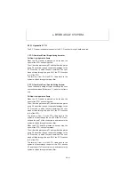
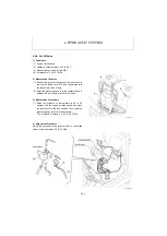
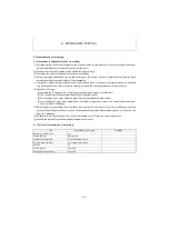
Cut-Off Valve
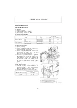
1) Conditions
(1)
Engine : rated speed
(2)
Hydraulic oil temperature : 150 to 60 °C
(3)
Pressure gauge capacity :
9.8 MPa
(4)
Set pressure : 2.5 to 2.7 MPa
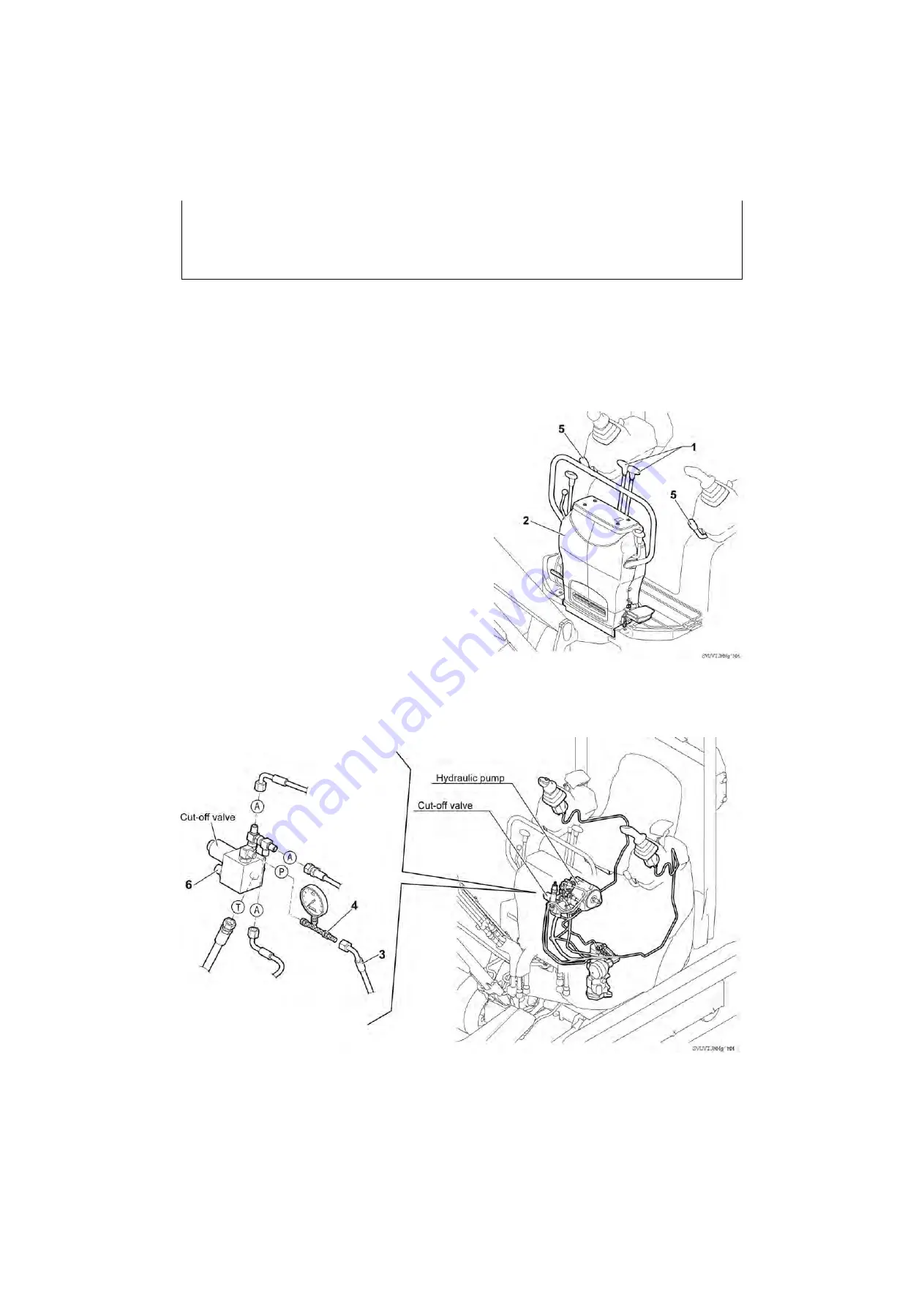
2) Measurement Position
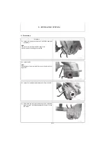
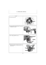
(1) Remove the grips
1
of the right and left travel levers,
remove the stand cover R
2
, and then disconnect
the connectors of the wiring.
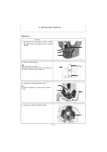
(2) Install the pressure gauge
4
to the hydraulic hose
3
between the pilot pump and the cut-off valve.
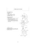
3) Measurement Procedure
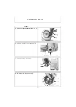
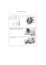
(1) Raise the hydraulic oil temperature to 50 to 60
degrees, run the engine at rated speed and place
the lock lever
5
in the lock position. Then, read the
pressure gauge
4
to check the pressure.
*The pressure is normal if it is
2.5 to 2.7 MPa.
4) Adjustment Procedure
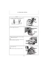
Adjust the pressure of the relief valve
6
to a specified
value, which is between 2.5 to 2.7
MPa.
Summary of Contents for ViO12-2A
Page 1: ...SERVICE MANUAL EXCAVATOR ViO12 2A...
Page 2: ......
Page 3: ......
Page 9: ......
Page 21: ......
Page 23: ......
Page 37: ......
Page 55: ......
Page 57: ......
Page 99: ......
Page 109: ...5 3 1 5 ELECTRIC SYSTEM 5 3 Wiring Diagram...
Page 114: ......
Page 117: ...6 HYDRAULIC SYSTEM 6 1 3...
Page 118: ...6 HYDRAULIC SYSTEM 6 1 4...
Page 119: ...6 HYDRAULIC SYSTEM 6 1 5 This Page Intentionally Left Blank...
Page 121: ...6 HYDRAULIC SYSTEM 6 1 7...
Page 122: ...6 HYDRAULIC SYSTEM 6 1 8...
Page 123: ...6 HYDRAULIC SYSTEM 6 2 1 6 2 Hydraulic Circuit Schematic...
Page 125: ...6 HYDRAULIC SYSTEM 6 3 2...
Page 126: ...6 HYDRAULIC SYSTEM 6 3 3...
Page 127: ...6 HYDRAULIC SYSTEM 6 3 4 This Page Intentionally Left Blank...
Page 129: ...6 HYDRAULIC SYSTEM 6 3 6...
Page 130: ...6 HYDRAULIC SYSTEM 6 3 7...
Page 131: ...6 HYDRAULIC SYSTEM 6 3 8 This Page Intentionally Left Blank...
Page 133: ...6 HYDRAULIC SYSTEM 6 3 10...
Page 134: ...6 HYDRAULIC SYSTEM 6 3 11...
Page 135: ...6 HYDRAULIC SYSTEM 6 3 12 This Page Intentionally Left Blank...
Page 137: ...6 HYDRAULIC SYSTEM 6 3 14...
Page 138: ...6 HYDRAULIC SYSTEM 6 3 15...
Page 139: ...6 HYDRAULIC SYSTEM 6 3 16 This Page Intentionally Left Blank...
Page 141: ...6 HYDRAULIC SYSTEM 6 3 18...
Page 143: ...6 HYDRAULIC SYSTEM 6 3 20 This Page Intentionally Left Blank...
Page 145: ...6 HYDRAULIC SYSTEM 6 3 22...
Page 147: ...6 HYDRAULIC SYSTEM 6 3 24 This Page Intentionally Left Blank...
Page 149: ...6 HYDRAULIC SYSTEM 6 3 26...
Page 150: ...6 HYDRAULIC SYSTEM 6 3 27...
Page 151: ...6 HYDRAULIC SYSTEM 6 3 28 This Page Intentionally Left Blank...
Page 153: ...6 HYDRAULIC SYSTEM 6 3 30...
Page 155: ...6 HYDRAULIC SYSTEM 6 3 32 This Page Intentionally Left Blank...
Page 157: ...6 HYDRAULIC SYSTEM 6 3 34...
Page 159: ...6 HYDRAULIC SYSTEM 6 3 36 This Page Intentionally Left Blank...
Page 161: ...6 HYDRAULIC SYSTEM 6 3 38...
Page 162: ...6 HYDRAULIC SYSTEM 6 3 39...
Page 163: ...6 HYDRAULIC SYSTEM 6 3 40 This Page Intentionally Left Blank...
Page 165: ...6 HYDRAULIC SYSTEM 6 3 42...
Page 166: ...6 HYDRAULIC SYSTEM 6 3 43...
Page 168: ...6 HYDRAULIC SYSTEM 6 3 45...
Page 169: ...6 HYDRAULIC SYSTEM 6 3 46...
Page 219: ...6 HYDRAULIC SYSTEM 6 7 8 1 4 3 8 7 12 10 10 15 a b c Loctite 262 0 30Nm 0 45Nm...
Page 348: ...7 ADJUSTMENT AND REPAIR 7 5 31 6 Control Levers Pilot valves Control valve...
Page 349: ...7 ADJUSTMENT AND REPAIR 7 5 32 7 Upperstructure Implement Bucket cylinder Arm cylinder...
Page 351: ...7 ADJUSTMENT AND REPAIR 7 5 34 9 Undercarriage High speed travel solenoid valve...
Page 359: ......
Page 360: ...CHAPTER 8 PERIODIC INSPECTION AND SERVICING 8 1 List of Periodic Inspection and Servicing 8 1...
Page 361: ......
Page 364: ...CHAPTER 9 FUEL LUBE OIL AND GREASE RECOMMENDED 9 Fuel Lube Oil and Grease Recommended 9 1...
Page 365: ......
Page 367: ......
Page 369: ......
Page 406: ...CHAPTER 11 REFERENCE DATA 11 1 Specifications for Attachment 11 1...
Page 407: ......

