6.
HYDRAULIC SYSTEM
6-
5
-
18
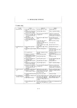
7. Troubleshooting
Trouble
Cause
Inspection
Measure
1. Abnormal noise
(1) Air sucked in due to low oil
level.
Check the hydraulic oil level.
Supply hydraulic oil.
(2) Increased suction pressure
loss due to filter clogging.
Check the filter element.
Clean or replace the element.
(3) Increased suction pressure
loss due to increased hydrau-
lic oil viscosity at low tem-
peratures.
Check the type and temperature
of hydraulic oil.
Replace the oil with proper
hydraulic oil, and operate the
pump at proper oil temperature.
(4) Input shaft rev. speed
exceeds specified value.
(5) Mechanical damage to bear-
ing, etc.
Check the rev. speed of input
shaft.
•Check the pressure which
causes overloading.
•Measure the contamination of
the hydraulic oil.
•Check if hydraulic oil is cloudy
due to water.
Readjust the rev. speed.
Replace the damaged part or
pump.
•Readjust pressure setting.
•Flush the circuit.
•Replace the hydraulic oil.
2. Insufficient flow vol-
ume
(1) Rev. speed drop of input
shaft.
Check the rev. speed of input
shaft.
Readjust the rev. speed.
(2) Excessively high oil tempera-
ture.
Check the oil temperature.
Stop the operation.
Check the oil temperature after
the oil cools down.
(3) Too high viscosity.
Check the oil type and oil tem-
perature.
Replace the oil with correct vis-
cosity hydraulic oil.
(4) Increased oil leak from
switching valve or actuator.
Identify the faulty actuator.
Replace switching valve or actu-
ator.
(5) Decreased pump displace-
ment efficiency.
Identify the faulty pump.
Replace the pump.
(6) Loosened horsepower set-
ting adjust screw.
Check for loose lock nut.
Set the horsepower again and
lock the screw.
(7) Air sucked in due to low oil
level.
Check the hydraulic oil level.
Supply hydraulic oil.
(8) Increased suction pressure
loss due to filter clogging.
Check the filter element.
Clean or replace the element.
(9) Increased suction pressure
loss due to increased hydrau-
lic oil viscosity at low tem-
peratures.
Check the type and temperature
of hydraulic oil.
Replace the oil with proper
hydraulic oil, and operate the
pump at proper oil temperature.
3. Pressure does not
rise
(1) Relief valve setting dropped. Measure the circuit pressure.
Reset the relief valve pressure.
(2) Increased oil leak from
switching valve or actuator.
Check for performance of each
actuator and abnormal heat in
the return oil piping.
Replace the switching valve or
actuator.
(3) Pump displacement efficiency
dropped.
Identify the faulty pump.
Replace the pump.
4. Overloading when
static load is applied
(1) Horsepower setting of pump
has risen.
Check the engine noise and the
work speed of the implement.
Listening to engine noise, reset
the horsepower with a wrench.
(2) Malfunction of controls.
Check for foreign substances
caught in the sliding areas of the
controls.
Repair or replace the part.
(3) Mechanical damage to bear-
ing etc.
Check for the abnormal heat and
noise in the housing around the
bearing.
Replace the damaged part or the
pump.
Summary of Contents for ViO12-2A
Page 1: ...SERVICE MANUAL EXCAVATOR ViO12 2A...
Page 2: ......
Page 3: ......
Page 9: ......
Page 21: ......
Page 23: ......
Page 37: ......
Page 55: ......
Page 57: ......
Page 99: ......
Page 109: ...5 3 1 5 ELECTRIC SYSTEM 5 3 Wiring Diagram...
Page 114: ......
Page 117: ...6 HYDRAULIC SYSTEM 6 1 3...
Page 118: ...6 HYDRAULIC SYSTEM 6 1 4...
Page 119: ...6 HYDRAULIC SYSTEM 6 1 5 This Page Intentionally Left Blank...
Page 121: ...6 HYDRAULIC SYSTEM 6 1 7...
Page 122: ...6 HYDRAULIC SYSTEM 6 1 8...
Page 123: ...6 HYDRAULIC SYSTEM 6 2 1 6 2 Hydraulic Circuit Schematic...
Page 125: ...6 HYDRAULIC SYSTEM 6 3 2...
Page 126: ...6 HYDRAULIC SYSTEM 6 3 3...
Page 127: ...6 HYDRAULIC SYSTEM 6 3 4 This Page Intentionally Left Blank...
Page 129: ...6 HYDRAULIC SYSTEM 6 3 6...
Page 130: ...6 HYDRAULIC SYSTEM 6 3 7...
Page 131: ...6 HYDRAULIC SYSTEM 6 3 8 This Page Intentionally Left Blank...
Page 133: ...6 HYDRAULIC SYSTEM 6 3 10...
Page 134: ...6 HYDRAULIC SYSTEM 6 3 11...
Page 135: ...6 HYDRAULIC SYSTEM 6 3 12 This Page Intentionally Left Blank...
Page 137: ...6 HYDRAULIC SYSTEM 6 3 14...
Page 138: ...6 HYDRAULIC SYSTEM 6 3 15...
Page 139: ...6 HYDRAULIC SYSTEM 6 3 16 This Page Intentionally Left Blank...
Page 141: ...6 HYDRAULIC SYSTEM 6 3 18...
Page 143: ...6 HYDRAULIC SYSTEM 6 3 20 This Page Intentionally Left Blank...
Page 145: ...6 HYDRAULIC SYSTEM 6 3 22...
Page 147: ...6 HYDRAULIC SYSTEM 6 3 24 This Page Intentionally Left Blank...
Page 149: ...6 HYDRAULIC SYSTEM 6 3 26...
Page 150: ...6 HYDRAULIC SYSTEM 6 3 27...
Page 151: ...6 HYDRAULIC SYSTEM 6 3 28 This Page Intentionally Left Blank...
Page 153: ...6 HYDRAULIC SYSTEM 6 3 30...
Page 155: ...6 HYDRAULIC SYSTEM 6 3 32 This Page Intentionally Left Blank...
Page 157: ...6 HYDRAULIC SYSTEM 6 3 34...
Page 159: ...6 HYDRAULIC SYSTEM 6 3 36 This Page Intentionally Left Blank...
Page 161: ...6 HYDRAULIC SYSTEM 6 3 38...
Page 162: ...6 HYDRAULIC SYSTEM 6 3 39...
Page 163: ...6 HYDRAULIC SYSTEM 6 3 40 This Page Intentionally Left Blank...
Page 165: ...6 HYDRAULIC SYSTEM 6 3 42...
Page 166: ...6 HYDRAULIC SYSTEM 6 3 43...
Page 168: ...6 HYDRAULIC SYSTEM 6 3 45...
Page 169: ...6 HYDRAULIC SYSTEM 6 3 46...
Page 219: ...6 HYDRAULIC SYSTEM 6 7 8 1 4 3 8 7 12 10 10 15 a b c Loctite 262 0 30Nm 0 45Nm...
Page 348: ...7 ADJUSTMENT AND REPAIR 7 5 31 6 Control Levers Pilot valves Control valve...
Page 349: ...7 ADJUSTMENT AND REPAIR 7 5 32 7 Upperstructure Implement Bucket cylinder Arm cylinder...
Page 351: ...7 ADJUSTMENT AND REPAIR 7 5 34 9 Undercarriage High speed travel solenoid valve...
Page 359: ......
Page 360: ...CHAPTER 8 PERIODIC INSPECTION AND SERVICING 8 1 List of Periodic Inspection and Servicing 8 1...
Page 361: ......
Page 364: ...CHAPTER 9 FUEL LUBE OIL AND GREASE RECOMMENDED 9 Fuel Lube Oil and Grease Recommended 9 1...
Page 365: ......
Page 367: ......
Page 369: ......
Page 406: ...CHAPTER 11 REFERENCE DATA 11 1 Specifications for Attachment 11 1...
Page 407: ......


