6.
HYDRAULIC SYSTEM
6-7-3
)XQGDPHQWDO5XOHV
*HQHUDO,QIRUPDWLRQ&RQFHUQLQJ3LORW&RQWURO8QLW&RQQHFWLRQ
When removing the pilot control unit, all openings must be plugged immediately to prevent any contamination of the
hydraulic system.
When replacing the pilot control unit, remove the plastic plugs from the openings and lines just before making the
connections.
Do not tighten connectors to a torque greater than that specified in the assembly instructions.
Check the hydraulic installation's oil quality and filtration capacity during all servicing/maintenance operations.
The use of teflon tape, hemp and joint filler is prohibited.
Hydraulic lines and connections must not be under any strain whatsoever.
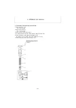
5HPRYDO,QVWDOODWLRQRIWKH3LORW&RQWURO8QLW&RQQHFWLRQ
*HQHUDO5HFRPPHQGDWLRQV
&$87,21
%HIRUHUHPRYLQJWKHSLORWFRQWUROXQLWIURPWKHPDFKLQHWKHEORFNDQGLWVVXUURXQGLQJVPXVWEHWKRURXJKO\FOHDQHG
ZLWKDKLJKSUHVVXUHFOHDQHU
1RLPSXULWLHVPXVWHQWHUWKHK\GUDXOLFV\VWHP3ODVWLFSOXJVDUHWREHILWWHGRQOLQHVDQGRULILFHVLPPHGLDWHO\IROORZ
LQJWKHLUUHPRYDO
:HDUSURWHFWLYHFORWKLQJDQGXVHVXLWDEOHHTXLSPHQWWRSUHYHQWDFFLGHQWVSDUWLFXODUO\FRQFHUQLQJ
WKHK\GUDXOLFIOXLG
6HWDOODFWXDWRUVFRQQHFWHGWRWKHPDFKLQHLQQHXWUDOSRVLWLRQRQWKHJURXQGDWORZHUOLPLWWR
DYRLG DFFLGHQWV ZKLFK FRXOG UHVXOW IURP XQFRQWUROOHG PRYHPHQWV RI WKH HTXLSPHQW ZKHQ WKH
K\GUDXOLFV\VWHPLVGLVFRQQHFWHG
:LWKWKHPDFKLQHRIIUHOHDVHWKHSUHVVXUHUHPDLQLQJLQWKHV\VWHPE\PDQLSXODWLQJDOORIWKHGLVWUL
EXWLRQVSRROV7KLVLVSHUIRUPHGE\PRYLQJWKHKDQGOHLQDOOGLUHFWLRQV
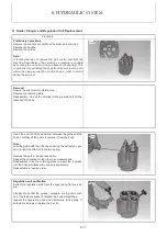
3LORW&RQWURO8QLW5HPRYDO
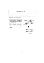
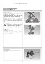
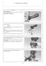
Immediately after disconnecting the lines from the control device, fit the sealing plugs. Make sure to collect any
pos-sible oil leakage in a suitable receptacle.
Unscrew the mounting screws and remove the control device.
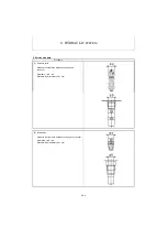
,QVWDOODWL\GUDXOLF3LORW&RQWURO8QLW
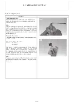
Contact faces must be perfectly clean.
Check the evenness of the support area on the machine (tolerance : 0.5 mm).
Check the condition of the line connector seals.
Clean the pilot control unit if it has been in storage for a long period of time.
Correctly place and secure the pilot control unit onto the machine with the mounting screw (maxi torque : 10 N
·
m).
Connect the lines to the control unit as per the connecting diagram and tighten to the torque specification (maxi
torque : 30 N
·
m).
Ensure that the hoses are not twisted or rubbed.
Once correctly installed, the unit can be placed into operation.
Summary of Contents for ViO12-2A
Page 1: ...SERVICE MANUAL EXCAVATOR ViO12 2A...
Page 2: ......
Page 3: ......
Page 9: ......
Page 21: ......
Page 23: ......
Page 37: ......
Page 55: ......
Page 57: ......
Page 99: ......
Page 109: ...5 3 1 5 ELECTRIC SYSTEM 5 3 Wiring Diagram...
Page 114: ......
Page 117: ...6 HYDRAULIC SYSTEM 6 1 3...
Page 118: ...6 HYDRAULIC SYSTEM 6 1 4...
Page 119: ...6 HYDRAULIC SYSTEM 6 1 5 This Page Intentionally Left Blank...
Page 121: ...6 HYDRAULIC SYSTEM 6 1 7...
Page 122: ...6 HYDRAULIC SYSTEM 6 1 8...
Page 123: ...6 HYDRAULIC SYSTEM 6 2 1 6 2 Hydraulic Circuit Schematic...
Page 125: ...6 HYDRAULIC SYSTEM 6 3 2...
Page 126: ...6 HYDRAULIC SYSTEM 6 3 3...
Page 127: ...6 HYDRAULIC SYSTEM 6 3 4 This Page Intentionally Left Blank...
Page 129: ...6 HYDRAULIC SYSTEM 6 3 6...
Page 130: ...6 HYDRAULIC SYSTEM 6 3 7...
Page 131: ...6 HYDRAULIC SYSTEM 6 3 8 This Page Intentionally Left Blank...
Page 133: ...6 HYDRAULIC SYSTEM 6 3 10...
Page 134: ...6 HYDRAULIC SYSTEM 6 3 11...
Page 135: ...6 HYDRAULIC SYSTEM 6 3 12 This Page Intentionally Left Blank...
Page 137: ...6 HYDRAULIC SYSTEM 6 3 14...
Page 138: ...6 HYDRAULIC SYSTEM 6 3 15...
Page 139: ...6 HYDRAULIC SYSTEM 6 3 16 This Page Intentionally Left Blank...
Page 141: ...6 HYDRAULIC SYSTEM 6 3 18...
Page 143: ...6 HYDRAULIC SYSTEM 6 3 20 This Page Intentionally Left Blank...
Page 145: ...6 HYDRAULIC SYSTEM 6 3 22...
Page 147: ...6 HYDRAULIC SYSTEM 6 3 24 This Page Intentionally Left Blank...
Page 149: ...6 HYDRAULIC SYSTEM 6 3 26...
Page 150: ...6 HYDRAULIC SYSTEM 6 3 27...
Page 151: ...6 HYDRAULIC SYSTEM 6 3 28 This Page Intentionally Left Blank...
Page 153: ...6 HYDRAULIC SYSTEM 6 3 30...
Page 155: ...6 HYDRAULIC SYSTEM 6 3 32 This Page Intentionally Left Blank...
Page 157: ...6 HYDRAULIC SYSTEM 6 3 34...
Page 159: ...6 HYDRAULIC SYSTEM 6 3 36 This Page Intentionally Left Blank...
Page 161: ...6 HYDRAULIC SYSTEM 6 3 38...
Page 162: ...6 HYDRAULIC SYSTEM 6 3 39...
Page 163: ...6 HYDRAULIC SYSTEM 6 3 40 This Page Intentionally Left Blank...
Page 165: ...6 HYDRAULIC SYSTEM 6 3 42...
Page 166: ...6 HYDRAULIC SYSTEM 6 3 43...
Page 168: ...6 HYDRAULIC SYSTEM 6 3 45...
Page 169: ...6 HYDRAULIC SYSTEM 6 3 46...
Page 219: ...6 HYDRAULIC SYSTEM 6 7 8 1 4 3 8 7 12 10 10 15 a b c Loctite 262 0 30Nm 0 45Nm...
Page 348: ...7 ADJUSTMENT AND REPAIR 7 5 31 6 Control Levers Pilot valves Control valve...
Page 349: ...7 ADJUSTMENT AND REPAIR 7 5 32 7 Upperstructure Implement Bucket cylinder Arm cylinder...
Page 351: ...7 ADJUSTMENT AND REPAIR 7 5 34 9 Undercarriage High speed travel solenoid valve...
Page 359: ......
Page 360: ...CHAPTER 8 PERIODIC INSPECTION AND SERVICING 8 1 List of Periodic Inspection and Servicing 8 1...
Page 361: ......
Page 364: ...CHAPTER 9 FUEL LUBE OIL AND GREASE RECOMMENDED 9 Fuel Lube Oil and Grease Recommended 9 1...
Page 365: ......
Page 367: ......
Page 369: ......
Page 406: ...CHAPTER 11 REFERENCE DATA 11 1 Specifications for Attachment 11 1...
Page 407: ......

