7. ADJUSTMENT AND REPAIR
7-2-1
4
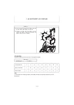
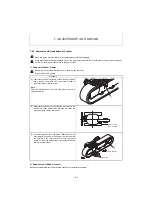
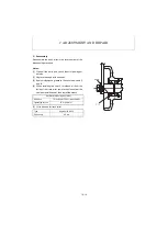
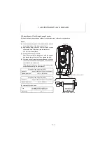
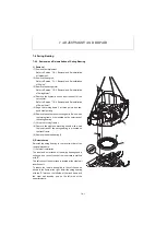
2) Reinstallation of Track Gauge Change Cylinder
Reinstall the track gauge change cylinder in the reverse order of the removal procedure.
Notes :
[1] Clean the square pipes of the crawler frames and the
square pipe holes of the lower center frame.
[2] Apply heavy-duty grease to the four sides of each
square pipe hole of the lower center frame over
200 mm
from the entrance.
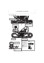
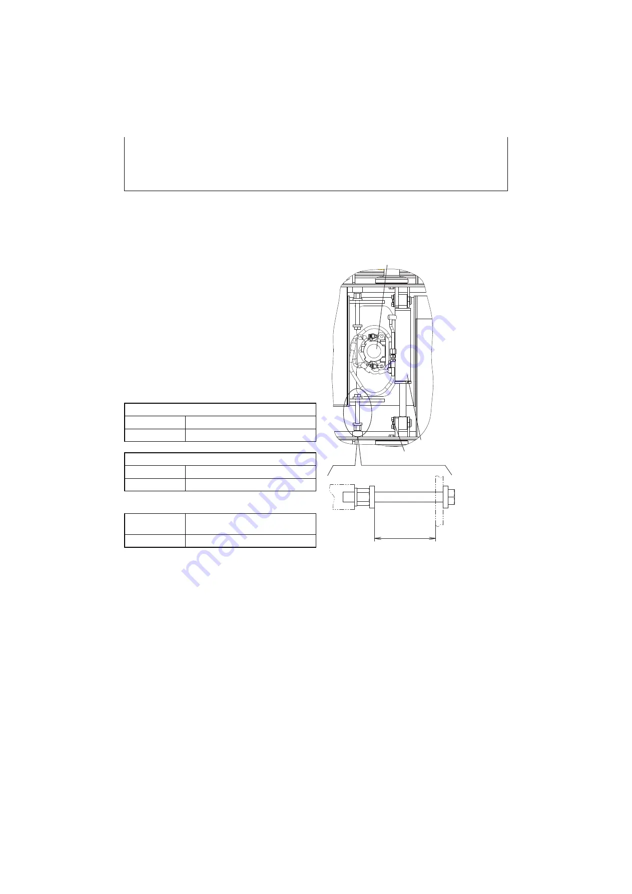
[3]
Stopper bolt setting
procedure:
After fully screwing the stopper nut onto the stopper
bolt, loosen the nut one turn. Then tighten the bolt.
[4] Place the hoses for the track gauge change cylinder in
the outermost and undermost position of all the hoses
connected to the swivel joint.
(This prevents the hoses from catching on any other
hose when narrowing the track frame.)
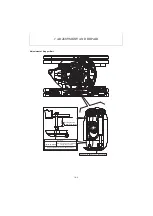
[5] Hydraulic oil to be used :
Stopper bolt and stopper nut (M16)
Adhesive
Apply Three Bond 1324 or its equivalent.
Tightening torque
166
,
7 to 205
,9
N•m
Stopper bolt and stopper nut (M16)
Adhesive
Apply Three Bond 1324 or its equivalent.
Tightening torque
44
,
1 to 58
,
8 N•m
Type
YANMAR SUPER HYDRO OIL
(VG 46 class) or its equivalent
Oil quantity
7
,
4 L
Swivel joint
Track gauge change cylinder
Stopper bolt and stopper nut
Set length at the
widest track gauge :
8
5 mm
Lock plate
Summary of Contents for ViO12-2A
Page 1: ...SERVICE MANUAL EXCAVATOR ViO12 2A...
Page 2: ......
Page 3: ......
Page 9: ......
Page 21: ......
Page 23: ......
Page 37: ......
Page 55: ......
Page 57: ......
Page 99: ......
Page 109: ...5 3 1 5 ELECTRIC SYSTEM 5 3 Wiring Diagram...
Page 114: ......
Page 117: ...6 HYDRAULIC SYSTEM 6 1 3...
Page 118: ...6 HYDRAULIC SYSTEM 6 1 4...
Page 119: ...6 HYDRAULIC SYSTEM 6 1 5 This Page Intentionally Left Blank...
Page 121: ...6 HYDRAULIC SYSTEM 6 1 7...
Page 122: ...6 HYDRAULIC SYSTEM 6 1 8...
Page 123: ...6 HYDRAULIC SYSTEM 6 2 1 6 2 Hydraulic Circuit Schematic...
Page 125: ...6 HYDRAULIC SYSTEM 6 3 2...
Page 126: ...6 HYDRAULIC SYSTEM 6 3 3...
Page 127: ...6 HYDRAULIC SYSTEM 6 3 4 This Page Intentionally Left Blank...
Page 129: ...6 HYDRAULIC SYSTEM 6 3 6...
Page 130: ...6 HYDRAULIC SYSTEM 6 3 7...
Page 131: ...6 HYDRAULIC SYSTEM 6 3 8 This Page Intentionally Left Blank...
Page 133: ...6 HYDRAULIC SYSTEM 6 3 10...
Page 134: ...6 HYDRAULIC SYSTEM 6 3 11...
Page 135: ...6 HYDRAULIC SYSTEM 6 3 12 This Page Intentionally Left Blank...
Page 137: ...6 HYDRAULIC SYSTEM 6 3 14...
Page 138: ...6 HYDRAULIC SYSTEM 6 3 15...
Page 139: ...6 HYDRAULIC SYSTEM 6 3 16 This Page Intentionally Left Blank...
Page 141: ...6 HYDRAULIC SYSTEM 6 3 18...
Page 143: ...6 HYDRAULIC SYSTEM 6 3 20 This Page Intentionally Left Blank...
Page 145: ...6 HYDRAULIC SYSTEM 6 3 22...
Page 147: ...6 HYDRAULIC SYSTEM 6 3 24 This Page Intentionally Left Blank...
Page 149: ...6 HYDRAULIC SYSTEM 6 3 26...
Page 150: ...6 HYDRAULIC SYSTEM 6 3 27...
Page 151: ...6 HYDRAULIC SYSTEM 6 3 28 This Page Intentionally Left Blank...
Page 153: ...6 HYDRAULIC SYSTEM 6 3 30...
Page 155: ...6 HYDRAULIC SYSTEM 6 3 32 This Page Intentionally Left Blank...
Page 157: ...6 HYDRAULIC SYSTEM 6 3 34...
Page 159: ...6 HYDRAULIC SYSTEM 6 3 36 This Page Intentionally Left Blank...
Page 161: ...6 HYDRAULIC SYSTEM 6 3 38...
Page 162: ...6 HYDRAULIC SYSTEM 6 3 39...
Page 163: ...6 HYDRAULIC SYSTEM 6 3 40 This Page Intentionally Left Blank...
Page 165: ...6 HYDRAULIC SYSTEM 6 3 42...
Page 166: ...6 HYDRAULIC SYSTEM 6 3 43...
Page 168: ...6 HYDRAULIC SYSTEM 6 3 45...
Page 169: ...6 HYDRAULIC SYSTEM 6 3 46...
Page 219: ...6 HYDRAULIC SYSTEM 6 7 8 1 4 3 8 7 12 10 10 15 a b c Loctite 262 0 30Nm 0 45Nm...
Page 348: ...7 ADJUSTMENT AND REPAIR 7 5 31 6 Control Levers Pilot valves Control valve...
Page 349: ...7 ADJUSTMENT AND REPAIR 7 5 32 7 Upperstructure Implement Bucket cylinder Arm cylinder...
Page 351: ...7 ADJUSTMENT AND REPAIR 7 5 34 9 Undercarriage High speed travel solenoid valve...
Page 359: ......
Page 360: ...CHAPTER 8 PERIODIC INSPECTION AND SERVICING 8 1 List of Periodic Inspection and Servicing 8 1...
Page 361: ......
Page 364: ...CHAPTER 9 FUEL LUBE OIL AND GREASE RECOMMENDED 9 Fuel Lube Oil and Grease Recommended 9 1...
Page 365: ......
Page 367: ......
Page 369: ......
Page 406: ...CHAPTER 11 REFERENCE DATA 11 1 Specifications for Attachment 11 1...
Page 407: ......

