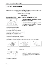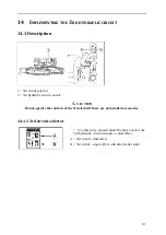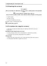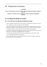
114
15.1.2 Procedure
1. Engage the truck's brake.
2. Position buttresses to immobilise the truck.
3. Position the ramp plates on the truck deck so that the centre of the truck and the centre of
the machine are aligned. Check that the left and right ramp plates are at the same level.
4. The angle between the ground and the ramp plates must be less than 15°.
1 = Ramps
2 = Wedge
3 = Stops
Note
Determine the spacing between the ramp plates based on the centre of the track
runners.
5. Place the accelerator pedal to idle position.
6. Direct the machine towards the ramp plates at low speed and load the machine onto the
truck. Do not use levers other than the side movement levers when travelling across the ramp
plates.
15.2 Immobilising the machine on the truck
Once the machine is in a suitable position on the truck, immobilise it as follows :
a = Wedge
1. Lower the blade to the ground.
Fold the bucket and the arm to the maximum, then lower
the boom to wedge the arm on a wooden block.
3. Turn the key to OFF position to switch off the engine
and disconnect the electrical circuit. Remove the key
from the ignition.
1 = Locking lever
2 = Left hand side
4. Lock the control levers with the locking lever.
Note
The hydraulic brake locks the rotation motor.
Summary of Contents for ViO38-6
Page 3: ......
Page 5: ......
Page 7: ......
Page 9: ......
Page 17: ......
Page 19: ...2 ...
Page 24: ...3 Warning labels 7 3 1 Location of the warning adhesive labels ...
Page 25: ...3 Warning labels 8 ...
Page 75: ...58 ...
Page 143: ...126 ...
Page 145: ...128 ...
Page 173: ...156 ...
Page 177: ...160 ...
Page 179: ...162 ...
Page 185: ...168 ...
Page 196: ...C Notes 179 ...
Page 201: ...MINI EXCAVATOR http www yanmar eu ...
Page 202: ...USER OPERATION AND MAINTENANCE MANUAL MINI EXCAVATOR ViO38 6 ...


