5 Description of the driving position
27
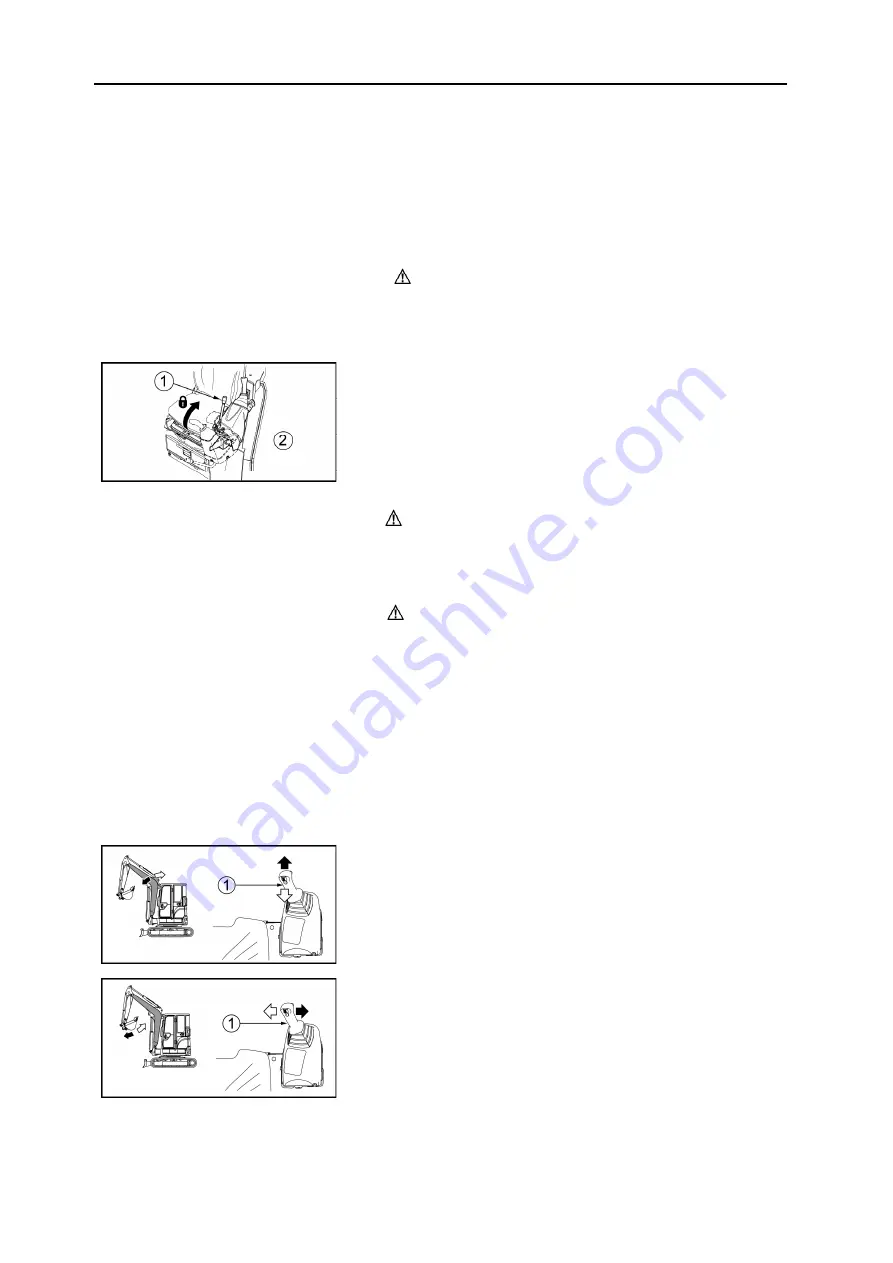
5.3.1 Locking lever
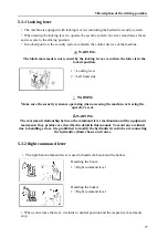
• The machine is equipped with locking lever(s) controling the hydraulic security system.
• When raising the locking lever to operate the security system, the lever stand raises for an
easier access to the driving position.
• In locked position, the security system condemn the control devices of the machine.
WARNING
The blade movement is not secured by the locking lever, even when the latter is in the
locked position.
1 = Locking lever
2 = Left hand side
WARNING
Make sure the security system is operating when accessing the machine or leaving the
operator's seat.
WARNING
The movement relationship between the command lever mechanism and the equipment
movements thay produce are described in detail in this manual. To avoid any accidents
due to handling errors, it is prohibited to modify the hydraulic circuit when reconnecting
the hydraulic cylinder hoses and valves.
5.3.2 Right command lever
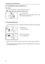
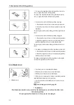
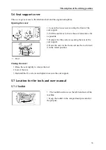
• The right hand command lever is used to handle the boom and the bucket.
Handling the boom
1 = Right command lever
Handling the bucket
1 = Right command lever
• When you release the lever, it returns to neutral position and the respective movements
stop.
Summary of Contents for ViO38-6
Page 3: ......
Page 5: ......
Page 7: ......
Page 9: ......
Page 17: ......
Page 19: ...2 ...
Page 24: ...3 Warning labels 7 3 1 Location of the warning adhesive labels ...
Page 25: ...3 Warning labels 8 ...
Page 75: ...58 ...
Page 143: ...126 ...
Page 145: ...128 ...
Page 173: ...156 ...
Page 177: ...160 ...
Page 179: ...162 ...
Page 185: ...168 ...
Page 196: ...C Notes 179 ...
Page 201: ...MINI EXCAVATOR http www yanmar eu ...
Page 202: ...USER OPERATION AND MAINTENANCE MANUAL MINI EXCAVATOR ViO38 6 ...


