background image

Summary of Contents for YM195

Page 1: ...DIESEL TRACTOR OPERATIONMANUAL MODEL YM195 3 YM195D I X LC...

Page 2: ...rsonal injury and carefully read the message that follows This stop symbol indicates important proper operation messages in this manual When you see this symbol be carefully read the message that foll...

Page 3: ...ard which would result in high probability of irreparable injury if proper precautions are not taken 2 WARNING denotes the hazard which would result in injury if proper precautions are not taken 3 CAU...

Page 4: ...1 httar Chuzr a d ar I 1 4 b p q OLUE kgc r mellurr 0 A1 a rllm lh cry a Srinutr MUMENUICE WHEN VOUR WACTOR 15 runinp up prod a s m NOT TO BE OPERATED FOR LONG TlME e Do not uu r top hk r f n c i m o...

Page 5: ...starting circuit is bypassed 4 Use approved rollover protective structure ROPS and seat belt Overturning a tractor without ROPS can result in death or injury Always adjust seat belt length to operato...

Page 6: ...rking brake securely When parking unavoidably on a slope position it at right angles to the slope and set parking brake securely and block both front and rear wheels 10 Do not drive near the edge of a...

Page 7: ...counterweight or wheel weights when suggested in operator s manual 16 Take all possible precautions as follows when leaving tractor unattended a Disengage PTO b Lower implement to ground C Shift all...

Page 8: ...ng Wear a suitable hearing protective device such as earmuffs or earplugs to protect against objectionable and uncomfortablenoises 20 Makesure a Tractor and implement are in good condi tion and proper...

Page 9: ...points on your equipment Keep others away from articulation joints hitches drawbar lift arms PTO drives cylinders etc Never stand or allow anyone else to stand between the tractor and implement unles...

Page 10: ...to PTO drive train and 3 point hitch C Adjusting cleaning and sewicing PTO driven implements 2 Make sure the tractor PTO RPM is matched to the implement s required RPM Do not drive or operate impleme...

Page 11: ...ter than its maximum travel speed in the highest gear and not more than 25 kmlh 16mph Before going down a steep hill shift to a low gear to control the tractor with little braking Never coast downhill...

Page 12: ...hain binders and be sure they are tight If chain bindersare not available use rope wire blocks or winch cable Check load after traveling a few kilometers and every 100km thereafter to make sure ties a...

Page 13: ...against the filler neck to prevent sparks and be sure t o replace the fuel tank cap 3 Do not overfill the tank or spill fuel I f fuel is spilled wipe off immediately Install fuel cap securely after r...

Page 14: ...can destroy clothing and burn skin Wear eye protection and rubber gloves when filling battery If you spill acid on yourself flush skin with water and apply baking soda or lime to neutralize acid Get m...

Page 15: ...IN PERIOD 22 5 OPERATING THE ENGINE 24 6 OPERATING THE TRACTOR 30 7 TRANSPORTING 52 8 FUEL AND LUBRICANTS 54 9 LUBRICATION AND MAINTENANCE 56 10 SERVICE 60 11 STORAGE 79 12 TROUBLE SHOOTING 81 13 OPTI...

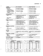
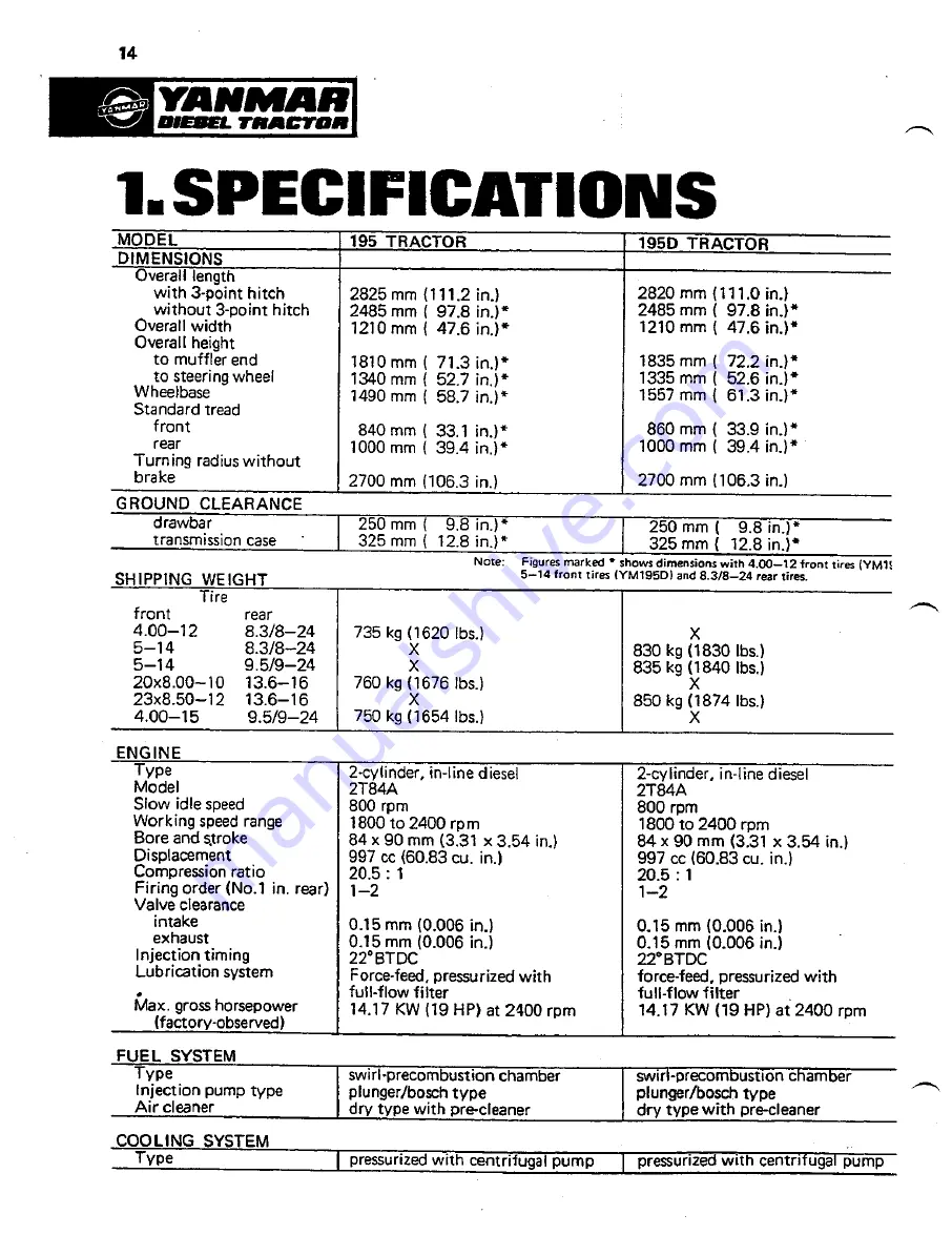
Page 16: ...system Max gross horsepower factory observed drawbar COOLING SYSTEM Type I pressurizedwith centrifugalpump I pressurizedwith centrifugal pump 2 cylinder in linediesel 2T84A 800 rpm 1800to 2400 rpm 84...

Page 17: ...disk dry 2 speed transmission driven with overrunning clutch 540 rpm 2200 engine rpm 1000 rpm 2200 engine rprn 35 mm 1 318inch uses transmission clutch TYpe Speeds Size Clutch Type I open center cons...

Page 18: ...9 519 24 rear tires Tire I I 280 rnrn 11 O in 373 rnrn 14 7 in X 770 kg 1698 lbs 810 kg 1786 Ibs X X 820 kg 1808 Ibs X X X 876 kg 1931 lbs 891 kg 1960 lbs X 1882 kg 1945 lbs 2 cylinder in line diesel...

Page 19: ...m 1000 rpm 2200engine rpm 35 mm 1 318 inch uses transmission clutch Type Relief pressure Pump with overrunning clutch 540 rpm 2200 engine rpm 1000 rpm 2200 engine rpm 35 mm 1 318inch uses transmission...

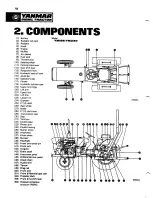
Page 20: ...link 23 Lower link 24 Drawbar 25 P T O shaft 261 Rear wheel 27 Brake 28 P T O shift lever 29 Transmission case 30 Step 31 Tool box 32 Clutch pedal 331 Pitman arm 341 Clutch housing 35 Starter motor 36...

Page 21: ...Model Yml95D VmSa0...

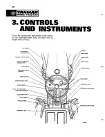
Page 22: ...1 i Pnsen TRACTOR 3 CONTROLS Study the controls and instruments of the tractor so you understand them fully and learn how to handle them correctly...

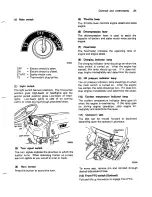
Page 23: ...ngine has started this lamp should go out If it does not stop engine immediately and determine the cause 9 Oil pressure indicator lamp The oil pressure indicator lamp should go on when the main switch...

Page 24: ...cause 3 Check engine oil and coolant levels more frequently Watch for any signs of leaks 4 Follow break in lubrication instructions on page 56 5 Until you become thoroughly familiar with the sound an...

Page 25: ...heel bolts and front axle bolts Check tightness of wheel bolts and axle bolts frequently during the first 100hoursof operation 1 Rear wheels A Rim to wheeldisk 0 Wheel disk to axleflange 2 2WD Front w...

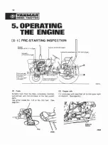
Page 26: ...all 5 P 11 3 U S gall 1YM195D ngine lubricatingoil O P 1 3 U S gal 1 1 Fuels 2 Engine oils Suitable fuels must be clean completely distilled Fill crankcase with specified oil to the upper mark well re...

Page 27: ...eplenish oil to the specified level When inserting dipstick rest it on the threads but do not screw it 6 Frontaxle oil YM195DIYM240D Capacity of front axle oil is 5 5 3 U S quarts for YM195D and 6 P 6...

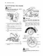
Page 28: ...ront PTO switch if it is equipped Push down the switch to disengagethe front PTO 5 Place hydraulic control lever in lower posi tion 6 Push throttle lever t o the maximum speed position Slow idk on As...

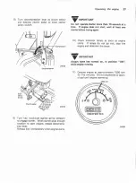
Page 29: ...r Release key immediately when engine starts Do not operate starter more than 10 seconds at a time If engine does not start wait at least one minite before trying again 10 Check indicator lamps as soo...

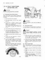
Page 30: ...releas ing the key it turns to ON position autornatically Ifengine does not srart within 10 seconds turn key to OFF position and wait at least one minute before trying again Fuel cup forthermostan Nev...

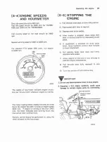
Page 31: ...ess thanactual total runninghours Periodic service should be performed by using the time indicated on the hourmeter 15 51STOPPING THE ENGINE 1 Pull throttle lwer back to slow idleposition 2 Placespeed...

Page 32: ...xample use a higher gear and lower engine speed for light load and use a lower gear and higher enginespeed for heavy load Depress clutch pedal and stop tractor before shifting either range shift lever...

Page 33: ...the tractor is stopped without placing the shift levers in neutral out of gear When disengaging depress the clutch quickly and when engaging release it slowly Do not restyour foot on the clutch pedal...

Page 34: ...ii it is equipped 4 Depressthe clutch pedal fully 6 Release clutch pedal slowly to engage the clutch 7 Adjust travel speed by throttle lever 7 Stopping the tractor When parking unavoidably on slopes c...

Page 35: ...This could result in loss of control in over speedingand damage to the DOnot operatetractor at high speeds or attempt to clutch turn with differential lock engaged When one wheel starts to spin engag...

Page 36: ...lamp Coolant temperature indicator lamp 3 Coolant temperatureindicator lamp Ifcoolant temperature indicator lamp goes on during engine operation engine is over heating and must be stopped at once Che...

Page 37: ...oo large an implement can damage the tractor Refer to your implement operator s manual for minimum and maximum horsepower requirements before attaching an implement 1 Position control system 1 Hydraul...

Page 38: ...a heavy implement is attached Adjust valve h valve can be use as stop lowering speed so that is slow enough to be valve at the slowest position safe 4 Feed back arm and rod The feed back arm and rod...

Page 39: ...1 75 in 8 19 6 rnrn 0 77 in C 22 1 mm 0 87 in D 683 rnrn 26 88 in 1 Installationof upper link Install upper link on the upper link hinge of tractor Implementsshould be positioned correctly by adjusti...

Page 40: ...ment hitch pin and secure it with linch pin If the hole and pin are not in line turn the turnbuckle of lift link R to adjust the height IMPORTANT When no implement is attached to hitch always use swin...

Page 41: ...ide to side Loosen lock nut and rotate leveling handle dl Side sway of implement is controlled by check chains Removesnap pins and rotate turnbuckles to lengthen or shorten chains asdesired and reinst...

Page 42: ...for the implement which has one double acting cylinder or two single acting cylinders or more 11 Ureof single acting cylinder The hydraulic system has a maximum pressure of 155 kg cma 2204 psi This m...

Page 43: ...uld be used by connecting the hydraulic lines to divider block of high pressure hydraulic line Divider block IMPORTANT when connecting hydraulic lines to the divider block see YANMAR dealer 6 4 DRAWBA...

Page 44: ...djustable only by turn ing offset up or down Proceed as in length adjustment but slide drawbir all the way out and turn it over 2 PTO guard 2 Power take off PTO AWARNING Do not use 1000 rum PTO sneed...

Page 45: ...h of driveshaft if necessary If the length of drive shaft is too long it causesto damage PTO shaft and transmission or implement when lifting the implement If the Iength of drive shaft is too short it...

Page 46: ...ing any adjustment Always place PTO shift lever in neutral position when not in use IMPORTANT Depress clutch pedal and stop tractor before engaging PTO Pull control lever back to engage 540 rpm speed...

Page 47: ...0 m 90 yards and before placing it under load retighten bolts to specifiedtorque C Check bolts after working three hours and again after 10 hours Retighten if neces sary d Check all bolts frequently a...

Page 48: ...ie rod clamps Tire 4 00 12 ISTD 5 14 STD 4 00 15 STD 6 14 STD Tread Range 24047 C Removebolts from front axle Fixedaxle 840mm 33 1 in 860 mm 5 3 9 in 840 mm 33 1 in 922 rnm 36 3 in d Slide axle knee t...

Page 49: ...7 0 in 2 Rear tread Rear wheel tread can be adjusted by re positioning or reversing the rims or by reversing the wheel disks Rear wheel tread can also be adjusted by reversing the complete wheels When...

Page 50: ...or wheel After adjustment of tread has been completed tighten inner attaching bolts disk to axle to 31 kg m 227 ft lbs torque for M16 llT bolt and to 20 kg m 147 ft lbs torquefor M16 7Tbolt The outer...

Page 51: ...IOU Tiremain Soil companion 8 Correct ballast C TOO little ballast Excessivespinning Power 10 Tire wear r Fuelwarre 1 Maximum rear ballast Do not overload tires Add no more weight than indicated in t...

Page 52: ...gallon CaCI If filled with water only the weight will lighten21 Do not useliquid ballastfor turf tires Do not use can iron weights if a liquid ballast is used Fill tires slightly above valve level 75...

Page 53: ...Do not use front ballast if the tractor is equipped with a front loader or other front mounted equip ments 2 Front bumper weights Up to five bumber weights can be installed Each weight approximately 2...

Page 54: ...d and couple pedals together before driving on a 5 Before descending a hill shift to a gear low road Avoid hard applications of brakes A enough to control speed without using towed load of more than t...

Page 55: ...Towing is illegal in some states 1 Be sure transmission hydraulic system oil level is to full mark on dipstick If tractor is to be towed with front end raised add one quart 1 2 of oil 2 Makesure diffe...

Page 56: ...under low ambient temperature as well as rarefied air may require use of a fuel with a high cetane number DIESEL FUELS Type of EnpineService Air Temperature Grade No idling Heavy load and high Below 5...

Page 57: ...nlv John Deere Tvpe 303 or Hv Grad Trans A mission and Hydraulic o i l or its equivalent in the CAUTION transmission hydraulicsystem Store fuel and lubricants out of reach of children 8 4 GREASE Your...

Page 58: ...upon re quirements The service intervalsare As required Daily or Every 10 hours Every 50 hours Every 100 hours Every 200 hours Every 300 hours Every 600 hours When operating under unusual conditions...

Page 59: ...ner Indimor lamps Brakes Clutch See page 67 Seepage68 See page 70 See page45 See page 48 Several strokes of grease gun See page 65 See page 72 See page 73 See page 78 See page 61 See page 0 Check fuel...

Page 60: ...k oil level Check tightness of steering system Check fan belt tension Replace belt if worn or damaged I Capacity and procedure See page 76 See page 70 Check the bulb by removing from the lamp holder I...

Page 61: ...em for leaks Correct a s necessary Ask YANMAR Front wheel hubs Renew front wheel hub grease dealer Radiator Engine crankcase Flush radiator Flush crankcase interior Ask YANMAR dealer Engine valve clea...

Page 62: ...ree travel IMPORTANT Do not operate tractor when clutch pedal free travel is lessthan 13 rnrn 112in Check clutch pedal free travel often especially for the tractor equipped with a loader or box scrape...

Page 63: ...rakes Free travel should not exceed 30 rnrn 1 2 in If free travel is excessive adjust linkage rod Loosen lock nuts and rotate turnbuckle to shorten rod Adjust free travel to 20 mm 0 8 in Tighten lock...

Page 64: ...m wheel cent pin 331 14 For four wheel drive model 1 Loosencenter pin mountingbolts 2 Insertshims to obtain correct play 3 Tighten center pin mountingbolts Mountingbolts 10 2 TIGHTENING BOLTS AND NUTS...

Page 65: ...lation manual for torques 1 Front axle center pin the tightening 6 Bolo between clutch housing and transmis sion case 33121 2 Tie rod ends 33123 Bolts M12 10 kg m 72ft lbs tightening torque 24067 3 Dr...

Page 66: ...64 Service 4 King pins 2WD Remove drain bolt before greasing 24073 5 Brake pedal shaft 6 Clutch pedal shaft 7 BPoint hitch 8 PTO control lever 9 Foot throttle pedal...

Page 67: ...operating under extremely dusty conditions check precleaner bowl several timesdaily Adr cleaner element 33033 2 Air cleaner Clean air cleaner element at least every 100hours Clean more often if a dir...

Page 68: ...nspectelement before reinstalling 3 3 Inspectingelement a Hold a bright light inside element and check carefully for holes Discard any ele ment which shows the slightest hole n b Be sure outer screen...

Page 69: ...g 1 Engine oil 1 Checking oil level Remove dipstick and wipe it clean Insert dipstick to rest on threads but do not screw it in Oil level should be between full mark upper and end of dipstick If low a...

Page 70: ...s tight C Install new filter element applying a thin film of oil to the sealing ring IMPORTANT The filter element has a special bypass valve Replace only with a genuine YANMAR filter element 3 Transmi...

Page 71: ...wer hydraulic lift to removetrapped oil b Clean or replace transmission oil filter as instructed in next step 4 before adding oil c After replacing filter and drain plug refill system with Transmissio...

Page 72: ...Refill with specified amount of SAE 90 gear oil e After changing oil check oil level Oil level should be level with upper mark on dip stick When checking oil level after refilling wait at least one ho...

Page 73: ...and ethylene glycol anti freeze fullseason type For non freezing weather you can use Summer Coolant Conditioner 3 Preparingfor cold weather If you drain cooling system to prevent freezing first add a...

Page 74: ...th engine stopped press belt midway between pulleys and measure deflection Belt should deflect 13 mm 0 5 in with around 9 ka 20 lbs force 2 Cleaningradiator screen Daily or even 10 hours clean radiato...

Page 75: ...ection nozzles yourself Special training and special tools are required See your YANMAR dealer The fuel system includes the fuel tank fuel strainer fuel pump fuel filter injection nozzles and the line...

Page 76: ...l injec tion nozzles are also empty loosen lines where they connect to injection nozzles Push throttle lever fully forward and operate starter until fuel runs from fittings Tighten lines n Whenever fu...

Page 77: ...ecifications first To avoid shock and burns disconnect battery ground cable before servicing any part of electrical system A DANGER Sulfuric acid in battery electrolyte is poisonous It can dest oyclot...

Page 78: ...ery on a tractor disconnect positive battery cable to starter to avoid damage the diodes of alternator Never apply FAST CHARGE to maintain long life of battery a Remove battery from tractor after disc...

Page 79: ...ne is running do not short cir cuit or ground the alternator and regulator terminals A correctly filled and well chargedbattery is d the best protection against freezing Check battery more often in wi...

Page 80: ...d charging indicator lamps Check the lamps daily when main switch is turned on If they are not glowing repalce them immediately 2 Coolant temperature indicator lamp The coolant temperature indicator l...

Page 81: ...ches normal ternpera ture Raise and lower hydraulic lift several times 7 Add 0 5 0 5 quart more of inhibitor to fuel tank 8 Add 0 5 Q 0 5 quart of inhibitor to engine crankcase 9 Seal end of air intak...

Page 82: ...emoving the tractor from storage 1 Removeall protective coverings 2 Remove clutch pedal block and allow clutch engage 3 Check tire inflation pressure 4 Install battery and connect cables Check alterna...

Page 83: ...olant temperature Engineoverheating Idle speed too slow Vent in fuel tank cap obstructed LOWcoolant temperature Clogged fuel filter Water dirt or air in fuel system Dirty or faulty injection nozzles D...

Page 84: ...pera ture indicator lamp or 1 sendingunits Reduce load or shift t o lower gear Serviceair cleaner Replacefilter element Useproper fuel See Engine Overheats Cover radiator screen See your YANMAR dealer...

Page 85: ...pping Improper type of fuel Clogged or dirty air cleaner Engineoverloaded 1 lnjection nozzlesdirty Drain fill crankcasewith oil I 68 of proper viscosity and quality REMEDY PAGE REFERENCE Replace filte...

Page 86: ...9 76 72 Clean and tighten connec tions Check electrolyte level and specific gravity Adjust belt tension or replace belt See your YANMAR dealer Allow engine to idle only when necessary Replace battery...

Page 87: ...ur YANMAR dealer Replaceswitch Check electrolyte level and specificgravity Use proper viscosity oil Clean and tighten loose connec tions Replacebelt Seat brushes Haveservice shop or YANMAR dealer reco...

Page 88: ...arm up system to normal operating temperature I Fill to proper level 1 27 I Adjust valve position 1 36 Check for leaks and tighten fittings and lines Open valve 66 36 I Use recommendedviscosity oil 1...

Page 89: ...g Worn gears and forks Transmission oil level low Adjust clutch pedal free tn l Worn or broken gears 60 Worn or broken forklslider Brakesadjusted unevenly Right and left tires inflated unevenly See yo...

Page 90: ...1 Front weights 2 Rear wheel weights 3 Foot throttle pedal...

Page 91: ...5 Work light Optional equipment 89 Rearview mirror e I Turn signal lights...

Page 92: ...0 10 4PR 13 6 16 4PR 27 8 50 15 2PR 11 2 10 24 4PR 12 Adjustable tread Factory option 13 Front PTO 14 9cc Hydraulic pump Factory option 15 Thermostat Factory option 16 Power steering 17 Took kit 18 SM...

Page 93: ...to the level indicated on the dipsticks Engine Transmission 2 Check engine oil leakage Confirm radiator is filled by the specified amount of coolant 1 Check tightness of bolls and nuts for mounting b...

Page 94: ...glow engaged competely not too heavy to turn and does 2 Check brake pedal free travel 3 Check effectivenessof parking 1 Grease 3 point hitch and other Inspection after operation 21 22 23 Greasing Fue...

Page 95: ......

Page 96: ...and serial number and 3 transmission number as well a s the name and number of each part This will insure that you always receive the parts you ordered Once again we urge you to carefully read the cp...

Page 97: ...95 Parts list 1 ENGINE...

Page 98: ...nchamber front Precombustion chamber rear Packing pre combustion chamber Insulator fuel injection valve Bonnet Flange fuel injection nozzle Support valve rocker arm Shaft decompression Element air cle...

Page 99: ...97 Pa list 2 HOOD THROTTLE...

Page 100: ...y clamp Clamp battery Cushion rubber Strainer fuel tank Battery Negativecable battery Positivecable battery Panel box Hourmeter Light ass y indicator Switch turn signal Button horn Cap horn button Swi...

Page 101: ...99 Pam list 3 FRONT AXLE...

Page 102: ...end ass y Oil seal Ball bearing Hub front wheel Tire ass y front Springwasher 14 Bolt M14x25 Ball bearing Washer 20 Nut M20 Cotter pin Cover front wheel hub Bracket front axle Oil plug Support king pi...

Page 103: ...4 STEERING CLUTCH BRAKES AND HYDRAULIC LINES...

Page 104: ...eeringwheel Lock nut Washer 12 5 x 22 x 2 3 Bush column Grommet Gear ass y steering Arm pitman Drag rod ass y Clutch disc ass y Pressure plate ass y Shaftwith lever clutch release Rod LH screwl clutch...

Page 105: ...103 Park lisr 5 TRANSMISSION REAR AXLE AND HYDRAULIC LIFT...

Page 106: ...T O 1 5 14 O ring P20 2 5 58 1 5 15 Cover Ll brake 1 5 59 Drawbar 1 5 16 Spring brakeshoe 4 5 60 Bracket drawbar 1 5 17 Anchor pin brake 2 5 61 Pin 22 x 75 drawbar 1 5 16 Brake shoe 4 5 62 Bolt MI4 x...

Page 107: ...105 Pam list 6 REAR FENDER SEAT HYDRAULIC CONTROL AND THREE POINT HITCH Only Y L I O D 21 4 Wheel drive...

Page 108: ...e shaft Lever A feed back Spring Shaft feed back Retainer Lever 01 feed back Lever control Guide control lever Stopper Wing bolt Hinge shaft Cover link Bush 13 x 15x 15 Stopper Key 3 x 13 Bar assist B...

Page 109: ...107 Pam list 7 ROLLOVER PROTECTIVE STRUCTURE ROPS...

Page 110: ...i 7 ROLLOVER PROTECTIVE STRUCTURE ROPS Q tylunit 1 1 1 2 2 1 1 No 7 1 7 2 7 3 7 4 7 5 7 6 7 7 Name of part ROPS Rear mount gusset RH Rear mount gusset LH Bottom attachment weldment Rubber pad Guard ex...

Page 111: ...109 Parts list 8 OPTIONAL EQUIPMENT Turn signal light 2 24111 Work light Throttle pedal Front weight rear wheel weight...

Page 112: ...Q wlunit 1 1 1 1 1 No 1 2 3 4 5 Throttle pedal ass y Name of part Work light ass y Lens work light Bulb 12V 20W Bolt M8 x 18 Nut M8 Thronle pedal Stay pedal Rod throttle pedal Circlip 20 Washer 8 1 Co...

Page 113: ...111 Paris list Reawiew minor Tools Underslung muffler...

Page 114: ...leblade type Grease pump Wrench 26 x 32 Name of pan Thermostart ass y Lead wire A thermostan Lead wire B thermostart Plug thermostart Header tank asfy Bracket header tank Band header tank Pipe fuel Bo...

Page 115: ...113 Parts list Adjustable front axle factory option 12 Adjustable rear wheels factory option 24120...

Page 116: ...8 Castle nut Washer 10 Cotter pin 2 5 x 25 Tie rod end ass y RL Tie rod end ass y LR Castle nut Cotter pin 3 x 25 O tylunit 1 1 1 1 2 2 4 4 4 2 2 2 2 1 2 2 2 2 2 Adjustable rear wheels 2 Wheel drive 2...

Page 117: ...115 P a m list Turf factory option Power steering...

Page 118: ...Front tire ass y turf Bolt M10x20 NutM10 Spring washer 10 Rear tire ass y turf Rear tire ass y turf Tire rear turf Tube rear tire turf Wheel rear turf Hose connection Bracket booster BoltMlOx28 Sprin...

Page 119: ...e starting 26 Front axle oil 25 Front PTO 21 Front weight 51 Front wheel toe in 47 Front wheel tread width 46 Fuel 24 54 Page Fuel filter 73 Fuel shut off valve 73 Fuel system service 73 Fuse 78 Greas...

Page 120: ...Tires 48 Shield master 42 Shifting transmission 30 Slow return valve 36 Specific gravity test 76 Specifications 14 Specifications fuel 54 Specifications lubricant 54 55 Speeds engine 29 Speeds ground...

Page 121: ...MEMO...

Page 122: ...YANMAR DIESEL ENGINE CO LTD YANMAR DIESEL AMERICA CORPORATION 951 CORPORATE GROVE DRIVE BUFFALO GROVE 1 L 60089 4508 U S A TEL 111 847 541 1900 FAX 1 847 541 2161...

Reviews: