background image


14 

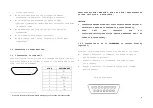
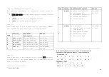
Press [START] key or short connect Pin 1 and Pin 2 as listed 
above, indicator will enter into automatic control status; 
press [STOP] key or short connect Pin 1 and Pin 3 as listed 
above, indicator will exit automatic control status; 
 

5.6 Manual work mode 

When scale is ready for weighing, short connect Pin 1 and Pin 
4 of control socket(Indicator I3 will be on),then short connect 
Pin 1 and Pin 6 of control socket, (Indicator I5 will be on),then 
it will start charge material. When the loaded material reaches 
OK range, then short connect Pin 1 and Pin 5 of control 
socket(Indicator I4 will be on),then short connect Pin 1 and 
Pin 7 of control socket, (Indicator I6 will be on),then it will 
start discharge material. This is one cycle in manual work mode. 
 

5.7 Automatic work mode 

When scale is ready for weighing, press [START] key or short 
connect pin 1 and pin 2 of control socket to enter into automatic 
control mode. Always short connect Pin 1 and Pin 6 of control 
socket(Indicator I5 will be always on) if there is no required 
for charge material, and indicator will begin charge 
automatically. Always


short connect pin 1 and pin 7 of control socket(Indicator I6 
will be always on)if there is no required for discharge material 
only when O6 is on. Then after o6 is on, indicator will begin 
discharge automatically. When indicator check that rest 
material in the hooper is within zero range, it will begin the 
next cycle automatically.


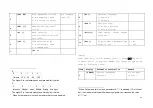
5.7 Input/Output hardware check 

At inner code display status, user can check whether the 
hardware of input/output connectors are good or not. When there 
is input for I1, then O1 will be on; when there is input for 
I2, then O2 will be on….when there is input for I6, then O1~O7 
will be on. If O indicator is not on, then it’s not good. 
 

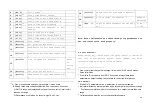
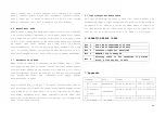
6.


OPERATION ERROR CODES 


Err  1


Can’t meet requirement of tare 

Err  2


Can’t meet requirement of zero 

Err  3


Incorrect input for date/time 

Err  4


EEPROM chip is damaged 

Err  P


Printing cable is not connected or printer 

error, print any key to exit 


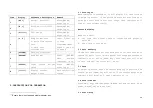
7.


Appendix 


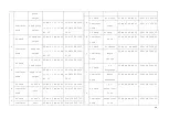
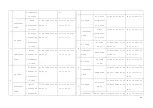
Command  

Note 

Format 

Example 

PC send 

handshake 

02 AD 41 XH XL 03 02 41 41 30 30 03 

A

Indicator 

send 

handshake

02 AD 41 XH XL 03 02 41 41 30 30 03 

B

PC send 

To read 

02 AD 42 XH XL 03 02 41 42 30 33 03 

Summary of Contents for XK3190-C601

Page 1: ...XK3190 C601 WEIGHING INDICATOR BATCHING VERSION MANUAL PLEASE READ THIS MANUAL VERY CAREFULLY BEFORE OPERATING Dec 2006 Specifications subject to change without prior notice ...

Page 2: ...n XK3190 C601 weighing indicator batching version adopts MCS 51 SCM and high speed Σ Δ A D conversion method with max 100 times s conversion speed It can make up batching scale with load cell and other mechanical parts applied in high speed and high precision weighing control occasion 1 2 Features Calibration and operation all by panel keys With parallel printing interface connected to stylus prin...

Page 3: ...ent 1 Turn scale off and cut off power before making any connections or disconnections Short connect PIN 1 AND PIN 2 PIN 6 and PIN 7 when connected to load cell with a 4 wire cable CAUTION Connection between load cell and indicator must be reliable shield wire must be connected to ground reliably Load cell and indicator are all static electricity sensitive devices measures must be taken to ensure ...

Page 4: ...en the frame indicator sends to PC is 0050 00 If the indicator displays 0 040KG then the frame indicator sends to PC is 000 040 B Command mode PIN ASSIGNMENT PIN ASSIGNMENT 1 RS422 OUTPUT 9 SCOREBOARD OUT 2 RS422 OUTPUT 10 SCOREBOARD OUT 3 RS422 IN 12 4 20mA I 4 RS422 IN 13 4 20mA I 6 RS232 RXD 14 CALIBRATION 7 RS232 TXD 15 CALIBRATION 8 GND Note1 RS422 output is optional Note2 Function of short c...

Page 5: ...m pc only triggers one operation hence several instructions should be sent from pc one by one to do these operations Instruction table is listed in appendix Connect indictor to scoreboard via 20mA current loop output Data is transmitted serially in binary code with baud rate 600 Data format is as listed below one group 0 1 2 3 4 5 6 7 8 9 10 START DATA Low is prior to high SIGN STOP Indicator send...

Page 6: ...he weight corresponding to 20mA 1 3 3 Connection with printer 25 pin interface Description for each pin is as listed in above table After connect to stylus printer indicator could print out weighing records accumulation value and formula 1 4 Layout at the back of various interfaces 2 TECHNICAL PARAMETERS AND SPECIFICATIONS Accuracy Class III N 3000 A D Conversion Method Σ Δ Input Signal Range 0mV ...

Page 7: ...utput touching capacity at AC 220V 0 5A Input Switch touching point close effective Operation Environment 0o 40o C Non condensed R H 90 Power Source AC220V 15 10 50HZ 2 2 3 LAYOUT AT FRONT AND DESCRIPTION Key board START key Press this key then indicator start working in automatic control status STOP key Press this key then indicator stop working in automatic control status ESC key Press this key ...

Page 8: ...DICATOR This is an input indicator It will be on when there is a short connect between pin 1 and pin 4 of control socket as listed in below table This input is usually given when weighing indicator works in manual control mode to start the charge control process I4 INDICATOR This is an input indicator It will be on when there is a short connect between pin 1 and pin 5 of control socket as listed i...

Page 9: ... will be on when weighing indicator is at the process of slow feeding for the first material O3 INDICATOR This is an output indicator It will be on when weighing indicator is at the process of fast feeding for the second material O4 INDICATOR This is an output indicator It will be on when weighing indicator is at the process of slow feeding for the second material O5 INDICATOR This is an output in...

Page 10: ...ge Stop Start Public I6 I5 I4 I3 I2 I1 When any of the pin from 2 to 7 is short connected to pin 1 it just gives indicator one kind of input corresponding input I indicator will be on Pin 8 to Pin 15 is for output description Pin 15 Pin 14 Pin 13 Pin 12 Pin 11 Pin 10 Pin 9 Pin 8 12V NOT OK OK Discharge Slow 2 Fast 2 Slow 1 Fast 1 O7 O6 O5 O4 O3 O2 O1 When indicator is at the process of one of the ...

Page 11: ...hese connection 6 Parameter A 0 outside code display 1 inner code display Parameter B 1 8 B 1 2 3 4 5 6 7 8 e 0 5 1 1 5 2 2 5 3 3 5 4 Parameter C D 0 5 C D 0 1 2 3 4 5 F S 0 2 4 10 20 100 Item Display Parameter description Remark 1 d Current date set Could set 2 t Current time set Could set 3 n Accumulation time Check only 4 A Accumulation value Check only 5 De1 0 Clear accumulation value or not4 ...

Page 12: ...rameter A is disabled If D of H is set as 1 then indicator will output 20mA analog signal when it reaches the value A set 3 FLt EF E AD parameter setting7 E AD sampling speed F AD filter intensity For example FLt 22 4 Adr Address for indicator8 1 26 5 bt Baud rate 0 4 0 600 1 1200 2 2400 3 48 00 4 9600 6 tod Communication mode 0 Continuously send 1 Command mode 7 Pt 8 PL Printing language 0 Englis...

Page 13: ...ameter set as 0 parameter t3 and t4 are disabled 14 Indicator will treat as discharge finish when tare weight is less than zero range Print and accumulation will only function when tare weight is more than zero range 15 Calibration head must be put on to save calibration data 2 Pt 0 Cycle times11 3 t0 12 Delay time before charge 4 t1 Delay time at fast feed finish 5 t2 Delay time at slow feed fini...

Page 14: ... zero indicator will be on 5 3 Tare At weighing status when the current display is positive and stable press TARE key will tare off the current weight and indicator will display 0 zero indicator is on 5 4 Date time set Press SET key and then press ENTER key and set date then press ENTER key and set time 5 5 Start Stop Item Display Parameter description Remark 1 dC Decimal point 0 3 Press ENTER aft...

Page 15: ...re is no required for charge material and indicator will begin charge automatically Always short connect pin 1 and pin 7 of control socket Indicator I6 will be always on if there is no required for discharge material only when O6 is on Then after o6 is on indicator will begin discharge automatically When indicator check that rest material in the hooper is within zero range it will begin the next c...

Page 16: ...41 45 30 34 03 PC send To zero 02 AD 46 XH XL 03 02 41 46 30 37 03 F Indicator Zero 02 AD 46 XH XL 03 02 41 46 30 37 03 PC send To start 02 AD 47 XH XL 03 02 41 47 30 36 03 G Indicator send start 02 AD 47 XH XL 03 02 41 47 30 36 03 PC send To stop 02 AD 48 XH XL 03 02 41 48 30 39 03 H Indicator send Stop 02 AD 48 XH XL 03 02 41 48 30 39 03 PC send To charge 02 AD 49 XH XL 03 02 41 49 30 38 03 I In...

Page 17: ... XH XL 03 02 41 4F 30 45 03 O Indicator send Print formula 02 AD 4F XH XL 03 02 41 4F 30 45 03 P PC send To print calibratio n rate 02 AD 50 XH XL 03 02 41 50 31 31 03 Indicator send Print calibratio n rate 02 AD 50 XH XL 03 02 41 50 31 31 03 PC send To read content of calibratio n rate Q Indicator send Send content of calibratio n rate 02 AD 51 NN XH XL 03 02 41 51 30 32 30 03 PC send To read par...

Page 18: ...NN C1 C2 C3 XH XL 03 02 41 55 30 32 35 35 31 36 03 PC send To clear accumulati on value 02 AD 56 XH XL 03 02 41 56 31 37 03 V Indicator send Clear accumulati on value 02 AD 56 XH XL 03 02 41 56 31 37 03 PC send To read date 02 AD 54 NN C1 C2 C3 XH XL 03 02 41 54 30 30 30 32 31 37 03 W Indicator send Send date 02 AD 54 NN C1 C2 C3 XH XL 03 02 41 54 30 30 30 32 31 37 03 PC send To read time 02 AD 58...

Page 19: ... C7 C8 XH XL 03 30 37 2D 32 36 31 45 03 PC send To write time 02 AD 5A C1 C2 C3 C4 C5 C6 C7 C8 XH XL 03 02 41 5A 30 39 3A 34 30 3A 32 36 31 32 03 Z Indicator send Write time 02 AD 5A C1 C2 C3 C4 C5 C6 C7 C8 XH XL 03 ...

Reviews: