5
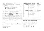
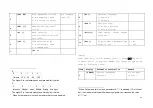
For group three, Sign bit is 1; G7~G0 is binary code;
From G0~G17 consists of 18 bit binary code, low prior to high.
with content of weighing data
•
Connect indicator to current display via 4~20mA
analog output (optional)
When indicator is at zero,then current display will show 0;
when indicator is at the weight corresponding to 20mA, then
current display will show 20mA. (Refer to parameter setting
for how to set the weight corresponding to 20mA).
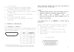
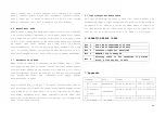
1.3.3 Connection with printer
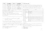
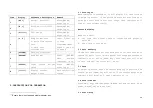
25-pin interface
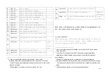
Description for each pin is as listed in above table. After
connect to stylus printer, indicator could print out weighing
records, accumulation value and formula.
1.4
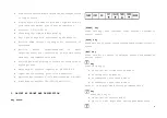
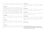
Layout at the back of various interfaces
2. TECHNICAL PARAMETERS AND SPECIFICATIONS
•
Accuracy: Class III,N=3000
•
A/D Conversion Method:
Σ
–
Δ
•
Input Signal Range: 0mV ~ 15mV
•
Net input signal range: 3mV ~ 15mV
•
Nonlinearity:
≦
0.01%FS
•
Temperature rate at FS:
≦
8PPM/
℃
•
Load Cell Excitation: DC5V, I
=
350mA
PIN #
ASSIGNMENT
PIN #
ASSIGNMENT
1 ST 7
D5
2 D0 8
D6
3 D1 9
D7
4 D2 11
BUSY
5 D3 25
GND
6 D4


