background image

Chapter 2 Installation 

2.1 Front and back view of the indicator 


Front View of the Indicator 


Back View of the Indicator


Summary of Contents for XK3190

Page 1: ...OPERATION MANUAL Edition Month year 1st October 2003 2nd June 2004 3rd 4th 5th ...

Page 2: ...1 ...

Page 3: ... Load Cell 1 350Ω 2 Display Display 0 999999 Interval 1 2 5 10 20 50 optional 3 Serial Communication Interface Optional Signal RS232C Transmission Distance 20m 4 Ambient Environment Power Supply AC 220v 15 10 50HZ 2 2 Ambient Temperature 0 40 Storing Temperature 25 55 Ambient Temperature 85 RH Warm up Time 10 15minutes Fuse 500mA 6 Weight 2Kg excluding battery 2 ...

Page 4: ...Chapter 2 Installation 2 1 Front and back view of the indicator Front View of the Indicator Back View of the Indicator 3 ...

Page 5: ... in thunderstorm frequently happening area 2 3 Serial Communication Interface Optional 1 Indicator communicate with computer by serial communication interface 2 Connection Indicator communication interface adopts 5 pin plug pin definition is as follows 5 pin TXD signal serial communication data 1 pin ground line 2 pin shield line The communication interface is 2pin plug 1 pin signal serial communi...

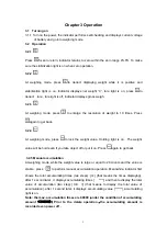
Page 6: ... weighing mode press to lock the weight value Holding light is on The weight value will be hold even if you take object off or put it on Press again to get back 3 2 5 Manual accumulation At weighing mode while the weight value is large or equal to 20 counts and the value is stable press to perform manual accumulation operation Meanwhile indicator first shows the total accumulating times two steps ...

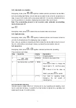
Page 7: ...aying value is lighted Note once you operate accumulating and fail to delete the accumulation amount at one of the unit unit diverting is not allowed unless you delete the accumulation amount 3 2 9 preset tare At weighing mode press together indicator performs tare presetting The procedure is as follows Step Operation display Explanation 1 Weighing display 2 Press P00000 Remind to input preset tar...

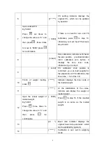
Page 8: ...ep Operation Display Explanation 1 Weighing display 2 Press d Setting of interval indicator displays the original interval which can be updated by operator 3 Input updated interval Eg 1 Press once to change the value to 1 Press for confirmation d 1 Parameter range 1 2 5 10 20 50 Press to confirm the updated one is as same as the original one 4 dP Decimal setting Indicator displays the original dec...

Page 9: ...herwise it go to step 9 9 LoAd F S calibration Zero position is confirmed you can load weights for the preparation of F S calibration that should be 1 2 of the F S 10 Finish of weight loading press Indicator displays the inner code of the loaded weight 11 At the stabilization of the value indicator will display the weight of loaded weight 12 Input the actual weight of loaded weight Eg 3000 Press t...

Page 10: ... you should take battery out Note red end is black end is Wrong connection will destroy indicator Note The built in battery should be fully charged before it is used for the first time 6 2 Only when you turn off the AC power and push start key battery works Displaying LouoL means the insufficient of voltage it needs charge 6 3 When you use the battery first time you should charge the battery for 2...

Page 11: ...d out the connecting line of indicator and external device You must cut off power supply of indicator before pulling out connecting line of load cell 7 7 During operation if trouble occurs operator must pull off the power supply plug immediately and user should return this indicator to our company for repair Non weighing manufacturer should not repair it or by yourself otherwise further destructio...

Reviews: