background image

16

SECTION 8:  SERVICE 

WARNING: 

Before servicing, repairing, or

inspecting, disengage all clutch levers and
stop engine. Wait until all moving parts have
come to a complete stop. Disconnect spark
plug wire and ground it against the engine to
prevent unintended starting. 

Engine

Refer to the engine manual for all engine 
maintenance procedures.

Augers

The augers are secured to the spiral shaft with two 
shear bolts and hex lock nuts. See Figure 22. If you 
hit a hard foreign object or ice jam, the snow 
thrower is designed so that the bolts may shear.

If the augers will not turn, check to see if the bolts 
have sheared. Replacement shear bolts and hex 
lock nuts have been provided with the snow 
thrower. When replacing bolts, spray an oil 
lubricant into shaft before inserting new bolts.

Shave Plate and Skid Shoes

The shave plate and skid shoes on the bottom of 
the snow thrower are subject to wear. They should 
be checked periodically and replaced when 
necessary. 

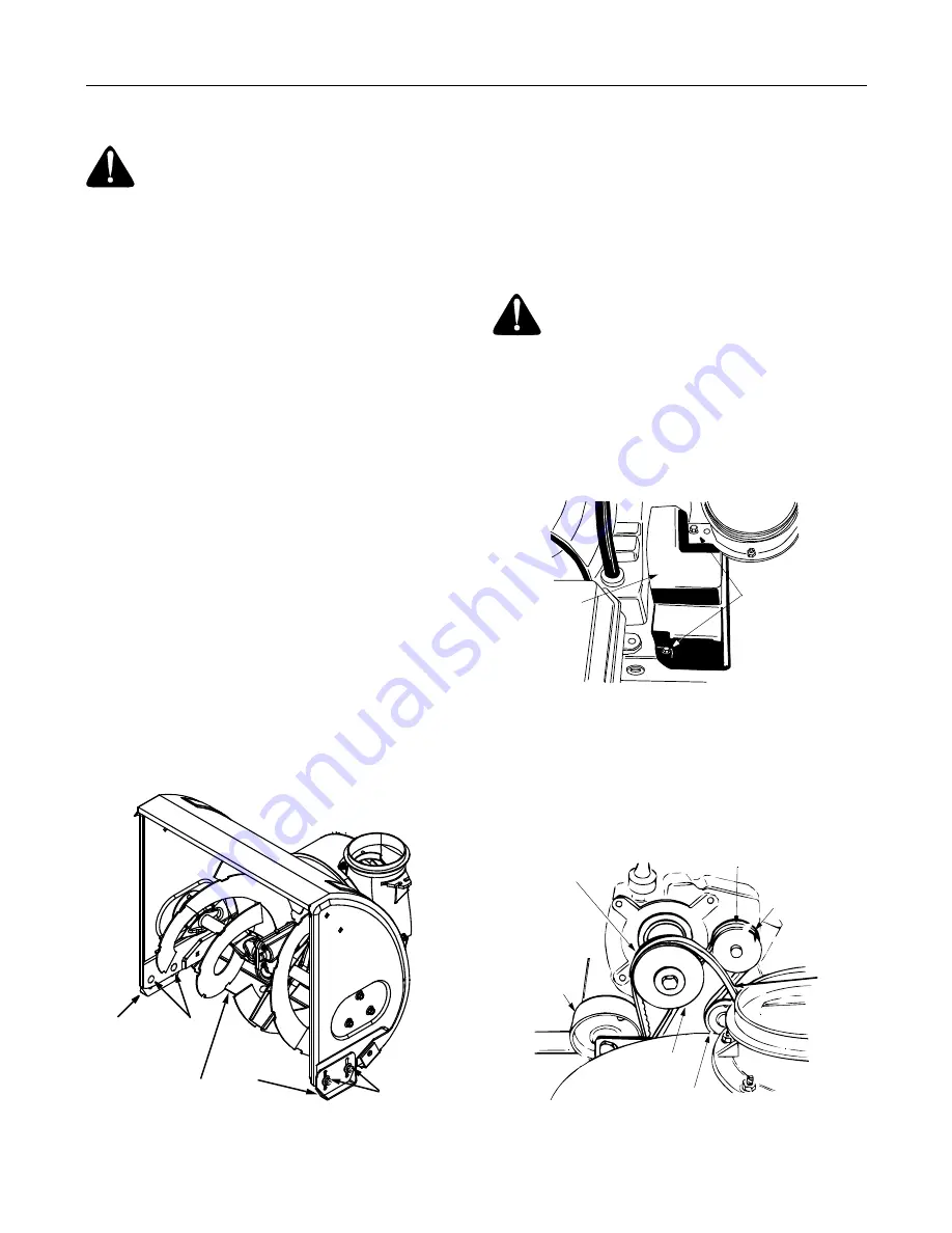
To remove skid shoes, remove the four carriage 
bolts, cupped washers and hex nuts which attach 
them to the snow thrower. Reassemble new skid 
shoes with the four carriage bolts, cupped washers 
(cupped side goes against skid shoes) and hex 
nuts. See  Figure 24.

Figure 24

To remove shave plate, remove the carriage bolts, 
cupped washers and hex nuts which attach it to the 
snow thrower housing. See Figure 24. Reassemble 
new shave plate, making sure heads of carriage 
bolts are to the inside of housing. Tighten securely.

Belt Removal and Replacement

WARNING: 

Disconnect spark plug wire

and ground it against the engine to prevent
unintended starting. Drain fuel into an
approved container or place a piece of plastic
film underneath the gas cap to prevent
gasoline from leaking. 

Auger Belts

Remove plastic belt cover from front of the engine 
by removing the two self-tapping screws. See 
Figure 25.

Figure 25

Drain gasoline from the snow thrower, or place a 
piece of plastic under the gas cap.Tip the unit up 
and forward so that it rests on auger housing.

Remove six self-tapping screws from the frame 
cover underneath the snow thrower.

Roll auger belt off the engine pulley. See Figure 26.

Figure 26

Carriage

Bolts

Skid 

Shoe

Skid
Shoe

Hex Nuts

Shave Plate

Self-Tapping

Screws

Cover

Belt

Belt

Drive

Drive 
Pulley

 Belt

Idler

Pulley

Engine
Pulley

Idler

Pulley

Auger

Summary of Contents for Series 611

Page 1: ...quipped with a spark arrester meeting applicable local or state laws if any If a spark arrester is used it should be maintained in effective working order by the operator In the State of California th...

Page 2: ...uthorized dealer You can locate the model number by standing behind the unit in the operating position and looking down at the frame below engine A sample model plate is explained below For future ref...

Page 3: ...s wear safety glasses or eye shields during operation and while performing an adjustment or repair to protect your eyes Thrown objects which ricochet can cause serious injury to the eyes 3 Do not oper...

Page 4: ...0 If situations occur which are not covered in this manual use care and good judgment Contact your dealer or telephone 1 800 800 7310 for assistance and the name of your nearest servicing dealer Maint...

Page 5: ...d nuts are provided for your convenience Store in a safe place until needed A 2 Hex Bolts A 710 3180 4 Lock Washers C 736 0119 2 Saddle I 784 5599 2 Hex Bolts B 710 3008 B 4 Hex Nuts D 712 3010 C 4 Ca...

Page 6: ...e to prevent unintended starting Attaching Handles Use Hardware Group A Place right handle in position against the snow thrower so that the flat side of the handle is against the frame Align the botto...

Page 7: ...ts E on each side and secure with lock washers C and hex nuts D See Figure 6 Figure 6 Attaching Speed Selector Plate Use Hardware D Assemble the speed selector plate to the outside of the handles as s...

Page 8: ...gaged up position may override the safety features of the machine Attaching Chute Assembly Use Hardware Group F Place chute assembly over chute opening with the opening in the chute assembly facing th...

Page 9: ...l and all four bolts which secure the handles to the frame are tight Final Assembly Adjustments Auger Control To check the adjustment of the auger control push forward on the left hand clutch grip dep...
Page 10: ...that you have adjusted correctly refer to the Adjustment section later in this manual Skid Shoes The space between the shave plate and the ground can be adjusted a For close snow removal on a smooth s...

Page 11: ...the right handle Squeeze the traction control grip to engage the wheel drive Release to stop See Figure 16 Throttle Control The throttle control is located on the engine It regulates the speed of the...

Page 12: ...prong receptacle at all times to avoid the possibility of electric shock Follow all instructions carefully prior to operating the electric starter Determine that your house wiring is a three wire gro...

Page 13: ...ds until you are familiar with the operation of the snow thrower Squeeze the auger control grip and the augers will turn Release it and the augers will stop Squeeze traction control grip and the snow...

Page 14: ...to Final Assembly and Adjustments on page 9 Carburetor WARNING If any adjustments need to be made to the engine while the engine is running e g carburetor keep clear of all moving parts Be careful of...

Page 15: ...purpose light grease at least once a season or after every 25 hours of operation IMPORTANT Keep all grease and oil off the friction wheel and drive plate Drive and Shifting Mechanism Remove rear cover...

Page 16: ...hem to the snow thrower Reassemble new skid shoes with the four carriage bolts cupped washers cupped side goes against skid shoes and hex nuts See Figure 24 Figure 24 To remove shave plate remove the...

Page 17: ...Rubber Replace the friction wheel rubber if any signs of wear or cracking are found Follow instructions below to replace the rubber WARNING Disconnect the spark plug wire and ground it against the eng...

Page 18: ...stops due to lack of fuel Drain carburetor by pressing upward on bowl drain located below the carburetor cover WARNING Drain fuel into an approved container outdoors away from open flame Allow engine...

Page 19: ...Gas cap vent hole plugged Exhaust port plugged Connect and tighten spark plug wire Remove ice and snow from cap Be certain vent hole is clear Clean following the engine manual Engine overheats Carbur...

Page 20: ...l 11 736 0351 Washer Flat 12 736 0369 Washer Flat 13 736 0445 Washer Flat 14 737 0168 Grease 15 741 0662 Bearing Flange 16 741 0663 Bearing Flange 17 618 0152 Ass y Complete 22 618 0120 Ass y Complete...

Page 21: ...0181 Lock Jam Nut 3 8 16 16 756 0569 Pulley Half 17 736 0242 Bell Washer 18 736 0505 Flat Washer 19 736 0507 Washer 20 754 0430A Belt 21 756 0967 Auger Pulley 22 736 0247 Flat Washer 23 736 0331 Bell...

Page 22: ...Thrower Model 611 1 2 3 4 5 6 7 8 9 10 11 12 16 17 13 14 15 19 9 18 20 22 23 25 21 24 23 22 18 26 28 27 32 31 30 34 29 33 18 16 35 38 36 37 39 40 43 42 41 40 39 44 45 Hook must be away from back of h...

Page 23: ...B Chute Adapter 22 712 0324 Hex Lock Nut 1 4 20 23 736 0463 Flat Washer 24 710 0451 Carriage Bolt 25 710 0703 Carriage Screw 1 4 20 x 75 26 710 0604 Hex Washer Screw 5 16 18 27 736 0169 Lock Washer 3...

Page 24: ...24 Snow Thrower Model 611 1 2 3 4 5 6 7 7 2 8 9 5 10 11 12 13 14 15 16 17 18 19 20 21 5 23 5 24 25 27 28 29 30 31 32 30 43 42 33 34 34 35 36 37 38 39 20 20 40 41 22...

Page 25: ...Screw 1 4 20 x 75 20 712 3027 Hex Lock Nut 1 4 20 21 732 0733 Shift Lever Spring 22 710 0788 Hex Washer Screw 1 4 20 x 1 0 23 736 0242 Bell Washer 24 726 0100 Push Cap 25 720 0201A Chute Knob 27 747 0...

Page 26: ...er Model 611 1 1 2 3 4 4 5 5 6 4 7 7 8 9 10 10 11 11 12 1 5 13 14 15 16 17 18 1 19 20 21 22 23 24 25 25 26 28 29 26 1 1 30 31 32 33 34 8 35 Blower Housing 36 20 20 37 37 38 39 40 27 41 41 41 For 16 wh...

Page 27: ...4 20 x 625 18 784 5590 Frame Shift Bracket 19 784 5638 Frame Cover 20 710 0599 Hex Washer Screw 1 4 20 21 736 0351 Flat Washer 760 ID x 50 OD 22 717 1445 Gear 23 714 0126 Key 24 717 1444 7 Tooth Shaft...

Page 28: ...on these items b Log splitter pumps valves and cylinders have a sepa rate one year warranty c Routine maintenance items such as lubricants filters blade sharpening and tune ups or adjustments such as...

Reviews: