background image

Summary of Contents for 13B-325-401

Page 1: ...state iaws it any If a spark arrester is used it should be maintained in effective working order by the operator In the State of Caiifornia the above is required by law Section 4442 of the California...

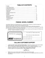
Page 2: ...model plate You can locate it by pivoting the seat frame upward and looking under the frame A sample model plate is shown below r XXX X XXX X XXX XXXXXXXXXXX This is where your model number will be Th...

Page 3: ...nd wait until blade s comes to a complete stop before a removing grass catcher or unclogging chute or b making any repairs adjusting or removing any grass or debris Mow only in daylight or good artifi...

Page 4: ...de where there is an open flame or spark such as a gas hot water heater space heater or furnace Never run a machine inside a closed area To reduce fire hazard keep the machine free of grass leaves or...

Page 5: ...riding mower could overturn and cause serious injury If operating a walk behind mower on such a slope it is extremely difficult to maintain your footing and you could slip resulting in serious injury...

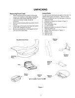
Page 6: ...te s way Loose Parts You will find the following loose parts in the crate To identify these parts see Figure 1 Remove loose parts very carefully so as not to damage or lose any 1 Steering wheel 2 Oper...

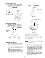
Page 7: ...crew _ 3 8 16 x 625 _ 710 0870 ATTACHING CONTROL KNOBS Truss Torx Machine i_ I_ Screw 710 3217 Hex Nut712 0142 _ _ Control Knobs 731 1918 Figure 2 NOTE Reference to front rear right or left hand side...

Page 8: ...minutes after filling with acid and later while you are charging the battery Follow the safety precautions mentioned previously Also remember to take added precaution as stated below while activating...

Page 9: ...minal with a hex bolt and nut provided See Figure 4 Route the battery drain tube through the opening in the mower frame See Figure 4 Hook the curved end of the hold down rod through the hole in the ba...

Page 10: ...l so that the cap fits snugly See Figure 9 Hex Bolt X Steering_ _ Bell Washer Wheel _ Steering Shaft f i Figure 8 Steering Wheel Insert Figure 9 Attaching Side Discharge Chute Your ridingmower is ship...

Page 11: ...the seat and secure with four self tapping screws See Figure 12 Align the tabs on the safety switch with the large cut out on the bottom of the seat push the safety switch in and turn clockwise to loc...

Page 12: ...the operator s eyes causing severe eye damage Always wear safety glasses before operating the mower or while performing any adjustments or repairs on it Throttle Choke Steering Wheel Control Shift Lev...

Page 13: ...he blade s and reverse downhill slowly Do not mow when children or others are around Never carry children Look down and behind before and while reversing Keep safety devices guards shields and switche...

Page 14: ...nd stop the unit With your right foot on the brake pedal move the shift lever to the neutral position Continuing to hold down the brake pedal with your right foot pull up the parking brake knob Make s...

Page 15: ...p If the grass catcher is full air does not flow through it allowing the ball to fall So if you see the white ball in the grasscatcher fill level indicator falling down you should stop the mower and e...

Page 16: ...rider mower The tractor should not move If the tractor moves_ adjust the brake WARNING Do net adjust the brake while the engine is running Be sure to block the wheels of the rider mower before making...

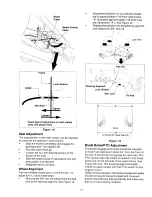
Page 17: ...e the seat forward or backward in the slot and position it as desired Retighten the four screws Wheel Alignment The front wheels should toe in t 16 5 16 inch To adjust toeqn follow these steps Remove...

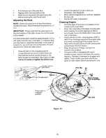
Page 18: ...e lock washer on the right side of the deck belt guard You will need a 7 16 socket wrench with 6 extension to remove this bolt Remove self tapping screw Remove hex nut lock washer Switch Figure 20 If...

Page 19: ...belt and reassemble following above instructions in reverse order Make sure that the belt is routed inside of belt keeper and the belt keeper is reassembled in the same location from where it was rem...

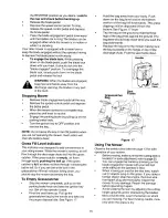
Page 20: ...en the bottom nut Loosen the second nut up or down as necessary See Figure 24 When desired adjustment is reached retighten the two nuts Adjust both sides if necessary Cleaning Engine Promptly wipe off...

Page 21: ...l from the heavy side until it balances evenly Reassembly Before reassembling the blade to the unit lubricate the spindle with light oil or engine oil Be sure to properly align star_fitting on blade w...

Page 22: ...the gas in either battery could explode Cleaning the battery Clean the battery by removing it from the unit and washing with baking soda and water solution If necessary scrape the battery terminals wi...

Page 23: ...nt Using a light oil or silicone coat the equipment especially any chains springs bearings and cables Battery Charge battery fully The battery loses some of its charge each day when the unit is not us...

Page 24: ...ider for cause such as foreign objects stuck in between deck and frame or belt path Remove obstruction and check for damage Replace belt it needed 2 Replace with proper belt Check Parts list in this m...

Page 25: ...ngs with water Charge with 6 AMP charger until fully charged If this does net work replace battery 4 Replace fuse following instructions on page 19 5 Make sure the black ground wire runs from engine t...

Page 26: ...troI Knob Yellow I Hex Nut 8 32 Pan Head Machine Screw 8 32 Hex Screw TT 1 4 20 x 50 NOTE For painted parts please refer to the list of color codes below Please add the applicable color code wherever...

Page 27: ...add the applicable color code wherever needed to the part number to order a replacement part For instance if a part numbered 700 xxxx is painted Oyster Gray the part number to order would be 700 xxxx...

Page 28: ...pping Screw 5 16 18 x 0 75 Hex Screw 5 16 18 x 0 75 Lock Nut 3 8 24 Hex Nut 1 2 13 Hex Nut Hex Nut Lock Nut 1 4 20 Lock Nut Cotter Pin Ref No 22 23 24 25 26 27 28 29 30 31 32 33 34 35 36 37 38 39 4O 4...

Page 29: ...to the list of color codes below Please add the applicable color code wherever needed to the part number to order a replacement part For instance if a part numbered 700 xxxx is painted Oyster Gray the...

Page 30: ...8 X 620 X 033 5 16 Washer Lock Washer Flat Washer Flat Washer 510 X 1 00 X 060 Flat Washer 406 x 1 25 x 10 _ef i Pad No No 30 736 0329 31 736 0608 32 736 3000 35 736 3019 34 736 3020 35 738 0255 35 73...

Page 31: ...Jam Nut 3 8 16 Gr 5 Hex Nut 5 16 18 Hex Cent Lock Nut 3 8 16 Hex Jam Nut 1 2 13 Gr 5 Cotter Pin Cotter Pin Cotter Pin Handle Grip Extension Spring 11 4 _of Pa_ No 17 732 0837 18 736 0119 19 736 0140 2...

Page 32: ...w Hex Screw 5 16 18 x 1 5 Gr 5 Thd Forming Scr 1 4_20x 75 Hex Nut 5 16 18 Cotter Pin Insulator Nut Plate Transaxle Support Bracket Spring Switch Shoulder Bushing Lock Washer 5 16 Fiat Washer 28 I D x...

Page 33: ...ex Net 3 8 24 Hex Nut 3 8 16 Hex Jam Nut 9 16 8 Gr 5 Square Key Variable Speed Pulley Assembly Extension Spring Extension Sprinng Lock Washer 7 18 I D o 18 19 20 21 22 23 24 25 26 27 28 29 iL _ _ 11 P...

Page 34: ...asher 531 X 1 062 X 134 Flat Washer 5 16 Fiat Washer 64 I D X 1 24 X 06 Fiat Washer 3 8 X 1 00 X 030 Bumper Rubber Bumper Extension Spring 14 1 I Ref I Pa_ No No P_ 20 726 0272 21 _725_0157 22 i714 04...

Page 35: ...lor codes below Please add the applicable color code wherever needed to the part number to order a replacement part For instance if a part numbered 700 xxxx is painted Oyster Gray the part number to o...

Page 36: ...Hex Screw 1 4 20 x 0 75 Battery Hold down Rod Hex Seres Nut 1 4 20 Lock Nut 1 4 20 i Wing Nut with Bell Washer Hex Nut 1 24 r 5 i Hose Clamp Ref Part No No 23 24 25 28 27 28 29 3O 31 32 33 34 35 36 37...

Page 37: ...nei Part No 2 710 0870 3 710 1017 4 720 0238 5 720 3026 6 i731 0511 I 7 i731 1691 i L___ 783 0410 Code _ _escription t Hex Hd TT Screw 1 4 20 x 0 5 Hex Washer Hd TT Screw 3 8 16 x 0 62 Torx Head AB s...

Page 38: ...n Grease Fitting Not Shown Flat Washer 635 x 1 589 x 060 Bell Washer 345 I D x 88 O D o6 Hairpin Clip Hex Screw 5 16 24 x 75 Rear Wheel 16 0 x 6 5 x 8 0 Front Wheel 11 0 x 4 0 x 4 0 _Flat Washer 5 8 D...

Page 39: ...0 28 736 0329 29 736 0343 30 738 0968 31 742 0651 32 747 0957 33 747 0972 34 754 0754 35 756 0627 36 783 0463 37 783 0529 38 783 0569A 39 783 0781 N 40 783 0594 __ Description Spindle Assembly Deck As...

Page 40: ...32 0841 22 732 0854 23 i736 0173 24 736 0329 25 783 0544 26 783 0575A l Code Description Flow Indicator Assembly N I Grass Bag Assembly Machine Screw 1 4 20 x 1 0 Machine Screw 1 4 20 x 0 5 Hex Screw...

Page 41: ...5 1657A 725 3234 BATTERY BOOT COVER 725 1727 TJ m 725 0267 RED WriT I YEL BLK _ _ c Z o Irl REVERSffSW 725 1643 ENGINE O p_ BRAKE SW YELJBLK i 725 1657A RED RED i BATTERY 725 1698 SOLENOID RED 7251426...

Page 42: ...Single Speed Transmission L H Part No 618 0251A Q3 J 42...

Page 43: ...2 13 761 0202 14 777 6318 Part No Code Description Differential Assembly Single Speed Drive Shaft assembly LH Brake Upper Housing Assembly Detent Shaft Assembly Brake Yoke assembly LH Hex Washer Hd TT...

Page 44: ...Department of MTD PRODUCTS iNC Transportation charges Transportation charges for the movement of any power equipment unit or attachment are the responsibility of the purchaser Units exported out of th...

Reviews: