background image

7

3

Assembling 

Your Tiller

WARNING

Do not put your 
fingers under the  
belt cover.
Maximum tire 

pressure under any 

circumstances is 

30 p.s.i. Equal tire 

pressure should be 

maintained on both 

tires.

Figure 3

Figure 4

Figure 5

Attaching Control Rod

•  Make sure the handle assembly is in the highest 

position. Refer to Know Your Tiller section.

•  Remove hairpin clips from control rod, (rubber 

washers to remain on control rod).

•  Insert the shorter, (angled), end of the control rod 

through the indicator bracket on the shift cover and 

secure with hairpin clip that was previously removed. 

See Figure 5.

•  Insert the longer end of the control rod through the 

hole in the gear selector handle and secure with 

hairpin clip.See Figure 6. 

Final Clutch Adjustment

IMPORTANT:

 Service the engine with oil and gasoline 

before checking this adjustment. Refer to the separate 

engine manual packed with your tiller for proper fuel and 

engine oil recommendations.
Position the tiller so the front counterweight is against 

a solid object, such as a wall. With the gear selection 

lever in NEUTRAL, start the engine. Refer to the 

separate engine manual.
Standing on the right side of the tiller, examine the belt 

(inside the belt cover). It should not be turning.

WARNING: Do not put your fingers 
under the belt cover.

If the belt turns without bail engaged, 

adjust by 

unthreading the internally threaded tube at the end 

of the cable a few turns clockwise (when standing in 

operator’s position) and then retighten the nut against 

the tube.

Now move the shift lever to FORWARD position. 

Carefully engage the clutch by lifting the clutch control 

bail against the handle. The wheels should spin.
If the wheels do not spin with the unit in forward, adjust 

by unthreading the tube at the end of the cable a few 

turns counter-clockwise (when standing in operator’s 

position) and then retighten the nut against the tube.
Recheck both adjustments, and readjust as necessary.

NOTE:  

A secondary cable adjustment is available if you 

reach the point that additional adjustment is needed. 

Remove the belt cover and move the hex nuts at the 

other end of the cable towards the end of the casing. 

Then readjust the hex nuts at the handle.

Tire Pressure

The tires on your unit may be over-inflated for shipping 

purposes. Reduce the tire pressure before operating 

the unit. Recommended operating tire pressure is 

approximately 20 p.s.i. (check sidewall of tire for tire 

manufacturer’s recommended pressure).

WARNING:  Maximum tire pressure 

under any circumstances is 30 p.s.i. 

Equal tire pressure should be main-

tained on both tires.

Internally

Threaded Tube

Slot Head Screw, Nut, 

& Flat Washers

Plastic Fitting

Slot Head Screw

Flat Washers

Nut

Internally

Threaded Tube

Threaded 

Eyebolt

Clutch Control

Nut

Rubber Washer

Control Rod

Indicator Bracket

Hairpin Clip

Idler Pulley Rod

Summary of Contents for 450 Series

Page 1: ...ined in effective working order by the operator In the State of California the above is required by law Section 4442 of the California Public Resources Code Other states may have similar laws Federal...

Page 2: ...orized service dealer Please do NOT return the unit to the retailer from which it was purchased without rst contacting Customer Support Customer Support If you have difficulty assembling this product...

Page 3: ...CHILDREN OR UNINSTRUCTED ADULTS TO OPERATE TILLER 5 SHUT OFF ENGINE BEFORE U NCLOGGING TINES OR MAKING REPAIRS 6 KEEP BYSTANDERS AWAY FROM M ACHINE 7 KEEP AWAYFROM ROTATING PARTS 8 USE EXTREME CAUTION...

Page 4: ...ry can occur when gasoline is spilled on yourself or your clothes which can ignite Wash your skin and change clothes immediately 7 Use only an approved gasoline container 8 Extinguish all cigarettes c...

Page 5: ...es Check their proper operation regularly 2 Check bolts and screws for proper tightness at frequent intervals to keep the machine in safe working condition Also visually inspect machine for any damage...

Page 6: ...pth stake assembly Place flat washer on the hex bolt and thread T knob onto the hex bolt Tighten securely See Figure 1 Tip the tiller back down so it rests on the tines Attaching Handle Assembly Remov...

Page 7: ...bail engaged adjust by unthreading the internally threaded tube at the end of the cable a few turns clockwise when standing in operator s position and then retighten the nut against the tube Now move...

Page 8: ...he reverse tine drive when tilling virgin ground sod or hard soil Use the forward tine drive when cultivating or tilling soft ground NOTE If difficulty is encountered in moving the gear selection hand...

Page 9: ...to enrich the fuel mixture in the carburetor when starting a cold engine This symbol points out important safety instructions which if not followed could endanger the personal safety and or property...

Page 10: ...ace the engine speed control in the START position Move choke lever to CHOKE position or if equipped push primer two 2 or three 3 times Wait about two 2 seconds between each push NOTE A warm engine ma...

Page 11: ...t the wheel drive only WARNING Do not push down on the handles so that the wheels are lifted off the ground while using the tine drive or the tiller could move backward and cause personal injury For b...

Page 12: ...remely dusty conditions Poor engine performance and flooding usually indicates that the air cleaner should be serviced To service the air cleaner refer to the separate engine manual packed with your u...

Page 13: ...Fill tank with clean fresh gasoline Fuel will not last over thirty days unless a fuel stabilizer is used Move throttle lever to start position Clean fuel line Refer to the engine manual packed with y...

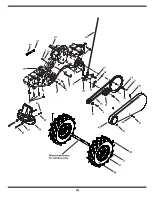
Page 14: ...13 29 35 16 53 35 16 46 31 28 12 45 17 17 44 36 6 3 33 15 27 5 36 43 4 20 40 21 1 34 18 10 42 23 7 22 36 8 47 32 37 50 25 10 9 24 36 51 34 45 26 41 36 35 16 29 19 49 44 33 14 35 16 2 14 28 35 16 14 11...

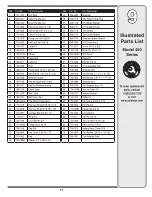
Page 15: ...fting Fork 22 717 1582 Spur Gear 44T 23 717 1583 Spur Gear 30T 24 717 1584 Spur Gear 30T 25 717 1585 Spur Gear 44T 26 717 1587 Spur Gear 44T Ref Part No Part Description 27 717 1594 Spur Gear 16T 28 7...

Page 16: ...23 10 1 60 61 37 62 25 34 27 64 30 39 63 26 32 36 33 31 29 66 26 41 30 30 24 28 35 40 26 49 44 50 59 51 65 53 55 56 54 57 58 44 46 42 4 9 11 16 6 3 14 7 19 5 17 2 60 61 12 15 12 38 21 22 67 70 70 68 6...

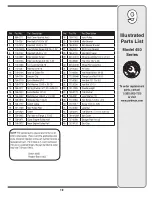
Page 17: ...69 Lock Washer 3 8 30 712 04063 Flange Nut 5 16 18 31 726 0106 Cap Nut 32 738 0849 Hex Screw 5 16 18 x 75 33 747 0432 Rod 34 750 0885A Spacer 322 x 625 x 2 0 Ref Part No Part Description 35 786 0090 S...

Page 18: ...18 33 35 4 38 37 34 24 7 41 3 16 15 13 21 25 14 1 11 2 8 6 27 5 39 20 31 32 29 Wheel shaft shown for reference only 36 18 12 26 43 42 17 28 40 44 45 9...

Page 19: ...ey Half 23 756 0972 Inner Engine Pulley Half Ref Part No Part Description 24 756 1162 Input Pulley 25 786 0064A Idler Bracket 26 786 0185 Belt Keeper Bracket 27 786 0187 Shift Cover Bracket 28 786 019...

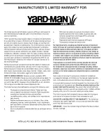
Page 20: ...the exterior finish due to use or exposure d Service completed by someone other than an authorized service dealer e MTD does not extend any warranty for products sold or exported outside of the United...

Reviews: