background image

Summary of Contents for 604G

Page 1: ...ing applicable local or state laws if any If a spark arrester is used it should be maintained in effective working order by the operator In the State of California the above is required by law Section 4442 of the California Public Resources Code Other states may have similar laws Federal laws apply on federal lands A spark arrester for the muffler is available through your nearest engine authorize...

Page 2: ...83 880 888 7318 Copy the model number here Copy the serial number here CUSTOMER SUPPORT Please doNOTreturntheunit to the retailer fromwhereit waspurchased withoutfirstcontactingCustomer Support If you have difficulty assembling this product or have any questions regarding the controls operation or maintenance of this unit you can seek help from the experts Choose from the options below En ine Visi...

Page 3: ...r repair to protect your eyes Thrown objects which ricochet can cause serious injury to the eyes 9 Wear sturdy rough soled work shoes and close fitting slacks and shirts Loose fitting clothes and jewelry can be caught in movable parts Never operate this machine in bare feet or sandals 10 Be aware of the mower and attachment discharge direction and do not point it at anyone Do not operate the mower...

Page 4: ...opes 5 Do not mow on wet grass Reduced traction could cause sliding 6 Do not shift to neutral and coast downhill Over speeding may cause the operator to lose control of the machine resulting in serious injury or death 7 Do not tow heavy pull behind attachments e g loaded dump cart lawn roller etc on slopes greater than 5 degrees When going down hilt the extra weight tends to push the tractor and m...

Page 5: ...de disengagement control If the blades do not stop within the this time frame your unit should be serviced professionally by your Troy Bilt dealer 4 Check brake operation frequently as it is subjected to wear during normal operation Adjust and service as required 5 Check the blade s and engine mounting bolts at frequent intervals for proper tightness Also visually inspect blade s for damage e g ex...

Page 6: ...ess of 15 degrees a rise of approximately 2 1 2 feet every 10 feet A riding mower could overturn and cause serious injury If operating a walk behind mower on such a slope it is extremely difficult to maintain your footing and you could slip resulting in serious injury Operate RIDING mowers up and down slopes never across the face of slopes t O ...

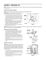
Page 7: ... operating the tractor Attachi The Steeri g Wheel 1 The hardware for attaching the steering wheel has been packed within the steering wheel beneath steering wheel cap Carefully pry off the steering wheel cap and remove the hardware 2 With the wheels of the tractor pointing straight forward place the steering wheel over the steering shaft Place the washer with the cupped side down over the steering...

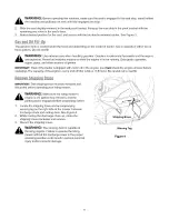
Page 8: ...ipes and other sources of ignition IMPORTANT Even if the tractor is shipped with motor oil in the engine you must check the engine oil level before operating The capacity of the engine s sump and oil filter is 62 oz 1 8 liters Be careful not to overfill RemoveShi B a88 IMPORTANT The shipping brace must be removed and discarded before operating your riding mower WARNING Make sure the riding mower s...

Page 9: ...eference It is very important to follow the instructions and operate the controls properly A E C D F G B H Figure 5 J K A Systems Indicator Monitor Ammeter G Cruise Control Button B PTO Power Take off Lever 14 Ignition Switch C Choke Control I Brake Pedal D Shift Lever J Drive Pedal E Throttle Control Lever K Deck Lift Lever F Parking Brake Button NOTE Any reference in this manual to the RIGHT or ...

Page 10: ... reverse to cause the tractor to move The further down the pedal is depressed the faster the tractor will travel The pedal will return to its original position when it is not depressed PTO Blade Engage Lever Engaging the PTO Blade Engage lever transfers power to the cutting deck ON _7_ or other separately available attachments The PTO lever must be disengaged Blade Stop when 1 starting the engine ...

Page 11: ...put of the engine s charging system Under normal operating conditions with engine at full throttle the ammeter should indicate positive charge Shift Lever t F The shift lever has three positions FORWARD F NEUTRAL N and REVERSE R These control the direction of movement of the tractor Depress the brake pedal and let the tractor stop before moving the shift lever to one of these three positions IMPOR...

Page 12: ...ck and are not designed to support the weight of the cutting deck CupHolder if equipped The tractor s cup holder is located on the fender to the left of the seat just to the rear of the parking brake lever Safe sted0ckSwitches The safety interlock system prevents the engine from cranking or starting unless the parking brake is engaged and the PTO lever is disengaged If this system should ever malf...

Page 13: ...clockwise to the OFF position 3 Remove the key from the ignition switch to prevent unintended starting Idvi I Tie Tractor Depress the brake pedal to release the parking brake Move the throttle lever into the FAST rabbit position To move forward place the shift lever in the FORWARD position then slowly depress the drive pedal until the desired speed is achieved To move in reverse place the shift le...

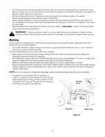
Page 14: ...awn where they act as a natural fertilizer On models with 46 inch decks where the mulch kit is packed separately within the tractor s crate follow the instructions included with the mulch kit Observe the following points for best results when mulching Never attempt to mulch if the lawn is damp Wet grass tends to stick to the underside of the cutting deck preventing proper mulching of the clippings...

Page 15: ...o shorten the drag link 4 Thread the ball joint away from the jam nut to lengthen the drag link 5 Replace hex nut and lock washer and retighten the jam nut after proper adjustment is achieved Grease Hex Nut Fitting Lock Washer Jam Nut Axle Ball Joint Pivot FBar Figure 8 NOTE Threading the ball joints too far on to the drag links will cause the front tires to toe in too far Proper toe in is between...

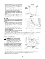
Page 16: ... the next step Loosen but do not remove the hex cap screw on the left deck hanger bracket See Figure 10 Hex Cap Screvt Figure 10 x x Adjustment Gear To balance the deck turn the adjustment gear located immediately behind the hex cap screw clockwise up or counterclockwise down See Figure 10 You will need an adjustable wrench for this step The deck is properly balanced when both blade tip measuremen...

Page 17: ...inished draining Refill the engine with Oil Drain Port approximately 62 oz 1 8 liters of new motor oil Air Cleaner Figure 12 Service the pre cleaner if so equipped and cartridge as instructed in the engine manual at the end of this manual SparkPlug Clean the spark plug and reset its gap once a season preferably at the start of each mowing season Refer to the engine manual for correct plug type and...

Page 18: ...e positive red wire When re installing the battery always connect the positive red wire to its terminal first followed by negative black wire Charging If the tractor has not been used for an extended period of time use a voltmeter or load tester to measure the charge The voltmeter should read 12 6 V or higher for adequate charge Otherwise charge the battery with an automotive type 12 volt charger ...

Page 19: ... the tractor locate the deck support pin on the rear left side of the deck See Figure 13 Pull the deck support pin outward to release the deck from the deck lift arm Rotate the pin slightly toward the rear of the tractor and release the pin into the hole provided Repeat the above steps on the right side of the tractor 6 7 8 9 Support Pin Figure 13 Move the deck lift lever into the top notch on the...

Page 20: ...ting position 7 Use a torque wrench to tighten the blade spindle hex flange nut to between 70 and 90 foot pounds 8 Gently slide the cutting deck from the right side out from underneath the tractor a sm ssb DdveBelt NOTE It is recommended that both drive belts be replaced at the same time 2 Remove the cutting deck as instructed earlier in this section After disconnecting the battery cables remove t...

Page 21: ...t that secures it to the transmission Use a second wrench to hold the hex nut on the bottom side of the pulley 3 Slide the belt offthe variable speed pulley as you lift the pulley up and out through the battery tray opening 4 Remove the rear idler pulley from the double idler bracket while unrouting the belt from around both the rear and the front idler pulley See Figure 15 5 Remove the hex bolt f...

Page 22: ...emove ignition key disconnect the spark plug wire s and ground against the engine before proceeding with job IMPORTANT The V belts on your tractor are specially designed to engage and disengage safely A substitute non OEM V belt can be dangerous by not disengaging completely For a proper working machine use factory approved belts All belts on the tractor are subject to wear and should be replaced ...

Page 23: ...k belt 6 Remove the belt from around all pulleys including the deck idler pulley 7 Route the new belts as in Figure 18 Figure 19 Remount belt guards removed earlier Model604H Engine Pulley Deck Idler Pulley PTO Idler Bracket mounted on tractor Right Hand Pulley beneath belt guard Double Pulley Left Hand o o NOTE Left hand belt covers not shown for clarity Center Pulley Figure 19 23 ...

Page 24: ...ect the negative terminal of the battery before storing the tractor NOTE Recharge the battery before returning it to service after storage Even if the tractor starts the engine charging system may not bring the battery upto a full charge unless it is recharged ASa8 sts Accessed s The following attachments and accessories are available for your lawn tractor See your local retail store or dealer for...

Page 25: ...h clean fresh gas Replace fuel filter if so equipped 4 Clear vent or replace cap if damaged 5 Drain fuel tank Refill with clean fresh gas 6 Replace air cleaner cartridge or clean pre cleaner if so equipped 1 Fill crankcase with proper capacity and weight of oil 2 Clean grass clippings and debris from around the engine s cooling fins and blower housing 1 Remove spark plug s and reset the gap at 030...

Page 26: ...SECTION 9 PARTSLISTFORMODELS 604G 604H 28 35_ 22 29 38 31 _18 1 34 3 1 13 12 10 11 5 26 ...

Page 27: ...w 8 32 x 375 Hex Nut 8 32 Dash Panel Parking Brake Button Throttle Control Lever Lock Nut 5 16 18 Speed Nut Hood Heat Shield RH Headlight Lens LH Headlight Lens Hood Support Rod Hood LH Side Panel RH Side Panel Lock Washer 1 4 Flat Washer 283 x 75 x 030 Dash Support Plate LH Flat Washer 349 x 1 0 x 063 Self tapping Screw 1 4 20 x 1 25 Self tapping Screw 5 16 18 x 75 29 30 31 32 33 34 35 36 37 38 3...

Page 28: ...Models604G 604H 24 32 26 7 28 ...

Page 29: ...e Lock Nut 3 8 16 Lock Nut 5 16 18 Hex Nut 1 2 13 Internal Cotter Pin Internal Cotter Pin E Ring Handle Grip Torsion Spring Extension Spring 84 x 4 6 Flat Washer 5 16 Lock Washer 1 2 Flat Washer 531 x 1 062 x 134 Flat Washer 51 x 1 12 x 06 Hex Cap Screw 5 16 18 x 62 Shoulder Screw 3 8 16 Hex Flange Bearing Snap Flange Bearing Lift Cable 16 16 Model 604G Lift Cable 15 62 Model 604H Lift Handle Roll...

Page 30: ...Models604G 604H 40 23 19 38 21 14 32 37 29 25 30 ...

Page 31: ...rag Link Jam Nut 7 16 20 Grade 2 Hex Nut 3 8 24 Grade 2 Flange Lock Nut 3 8 16 Flange Lock Nut 7 16 20 Flange Lock Nut 5 16 18 Steering Gear 11 90 Ratio Steering Pinion Gear Ball Joint 7 16 20 Lock Washer 3 8 Flat Washer 51 x 1 12 x 06 Steering Shaft 625 OD x 24 4 Plastic Bushing 38 ID Hex Flange Bearing 5 8 Shoulder Spacer 38 ID Steering Wheel Soft Grip Three Spoke Steering Wheel Cover LH Axle As...

Page 32: ...2 _27 _75 41 47 67 55 4s _ 46 49 IMPORTANT For a proper working machine use Factory Approved Parts V belts are designed to engage and disengage safely A substitute non OEM V belt can be dangerous by not disengaging completely 68 66 1_51 32 ...

Page 33: ...Pin Hex Lock Nut 3 8 16 Flange Lock Nut Cotter Pin Push Nut Compression Spring Extension Spring Control Pad Brake Pad Flat Washer Flat Washer Hairpin Clip Cotter Pin Hairpin Clip Cotter Pin Shift Knob Ball Joint Extension Spring Spring Clip Extension Spring Extension Spring Lock Washer 3 8 Grease Shoulder Spacer Shift Rod Brake Rod Idler Adj Rod Spacer Transaxte Spacer V Belt V Belt Flat Idler Pul...

Page 34: ...Models604G 604H 6 13 4 10 9 12 11 14 11 12 17 15 3 16 18 19 22 23 t J 20 21 J J J J J 28 29 27 26 25 34 ...

Page 35: ...ing Screw 1 4 20 x 1 625 Upper Housing Input Shaft Needle Bearing 625 x 813 x 495 14 tooth Bevel Pinion Retaining Ring 437 Sleeve Bearing 75 x 1 0 x 1 0 Seal 75 x 1 0 x 125 Differential Assembly Flange Bearing 5 8 x 3 4 x 3 4 42 tooth Bevel Gear 42 tooth Bevel Gear Clutch Collar Flat Washer 70 x 1 125 x 031 Drive Shaft Thrust Washer 1 0 x 632 x 0 Flange Bearing 5 8 x 3 4 x 15 16 Detent Shaft Assem...

Page 36: ...Models604G 604H 51 _2 _53 4 17 78 58 59 64 34 30_ Model 604H 16 24 39 10 28 _25 _9 Model 604G 14 23 _26 36 ...

Page 37: ...Pulley Idler Pulley Bracket Deck Stop Bracket Stop Flat Washer Belt Guard Pin Lock Nut Push Nut Flange Lock Nut Hex Nut 5 16 18 Cotter Pin Cotter Pin Speed Nut PTO Knob Belt Guard Belt Guard Extension Spring Flat Washer Lock Washer Flat Washer Lock Washer Belt Washer Flat Washer Flat Washer Flat Washer Spacer Hex Split Flange Bearing Handle Deck Engage 42 43 44 45 46 47 48 49 5O 51 52 53 54 55 56 ...

Page 38: ...0271 746 1086 DESCRIPTION Self tapping Screw 8 18 x 5 Self tapping Screw 1 4 20 x 5 Self tapping Screw 5 16 18 x 625 Screw 10 32 x 625 Socket Cap Screw 5 16 18 x 625 Self tapping Screw 3 8 16 x 1 25 Hex Nut 3 8 16 Exhaust Gasket Hose Clamp Cable Tie not shown Flat Washer Casing Clamp Fuel Line Hose Muffler Deflector Muffler Twin Inlet RH Exhaust Pipe LH Exhaust Pipe Oil Drain Valve Oil Drain Hose ...

Page 39: ... RED YEL BLK ORGJW_T II PTO SWITCH 725 1657A f SOLENOID 725 1426 FUSE 20 AMP FUSE 20 AMP SEAT SWITCH 725 1303 725 1439 BRAKE SWITCH 725 1657A Ammeter MECHANICAL REVERSE KILL KEY SWITCH 725 1741 OFF G M A1 RUN 1 B At L A2 RUN 2 B A1 START B S A1 O _ D i CPJ m PARKING BRAKE INDICATOR LIGHT 1 KEY SWITCH OFF 2 PTO OFF 3 TRACTOR UNOCCUPIED 4 BRAKE SWITCH OFF ...

Page 40: ...Model604G 61 63 23 _ 16 17 6O 2 10 37 24 _8 15 _I0 45 C 37 3 18_ J 4O 16 5O _ _54 i 51 35 49 4O ...

Page 41: ...r Pulley 3 5 Double Pulley 5 0 Self tapping Screw 1 4 20 x 4 0 712 0337 712 0417A 712 0431 712 0429 712 3006 712 0324 714 0470 716 3020 717 04074 726 0233 Hex Nut 5 8 18 Hex Flange Nut 5 8 18 Flange Lock Nut 3 8 16 Flange Lock Nut 5 16 18 Hex Nut 1 4 20 Hex Lock Nut 3 8 16 Cotter Pin 1 8 x 1 25 Internal Snap Ring Deck Adjustment Gear Push Nut 25 x 5 44 746 0970 45 783 1291 46 711 1534 47 731 2363 ...

Page 42: ...Model604H 41 24 21 1 32 2O 17 2 43_ _ _ lO 44 1 34 13 28 42 4 37 12 _ 1 42 ...

Page 43: ...ock Nut 1 2 13 Cotter Pin Gear Deck Adjustment Push Nut Compression Spring Extension Spring Deck Wheel Lock Washer Bell Washer Ref No 25 27 28 29 30 31 32 34 35 36 37 38 39 40 41 42 43 44 45 46 47 48 49 Part No Description 736 0760 737 3007 738 0372B 738 0373 742 0611A 742 0612A 747 1116 754 04033 756 1229 771 11725A 783 0141 783 0142 783 0805C 783 1025 783 1348A 783 1421 711 0792 732 0602A 703 16...

Page 44: ...s deck adjustments and normal deterioration of the exterior finish due to use or exposure Service completed by someone other than an authorized service dealer e f g MTD does not extend any warranty for products sold or exported outside of the United States its possessions and territories except those sold through MTD s authorized channels of export distribution Replacement parts that are not genui...

Reviews: