background image

10

SETUP & INSTALLATION

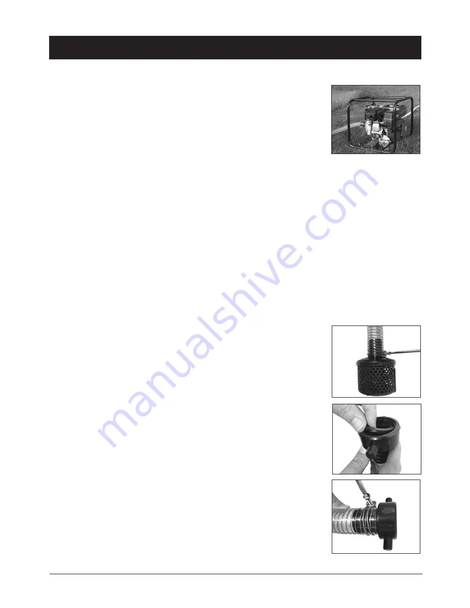
Positioning The Pump

1. Place the pump close to the water that is required to be pumped (Fig. 1).

Note: 

Ensure the pump is no further than 5m away from the water's edge.

2. Fill the engine crank case with oil (not included).

Note: 

SAE 10W-30 oil is recommended, refer to the maintenance section for more

information.

Suction Inlet
Connecting Hose or Pipe to the Suction Inlet

Note: 

Keep all hoses short and as straight as possible, failure to do so may decrease the pressure pumps performance.

Note: 

It is recommended that a filter (27) and check valve (not included) is installed at the end of the suction hose or pipe,

in order to prevent long priming periods and unnecessary damage as a result of stones and solid foreign materials
entering the pump.

Note: 

Reinforced or ridge suction hoses are required on the suction line to prevent the pipe from collapsing due to

pressure from suction.

Caution: 

All connections must be air tight, failure to do so may result in an air leak which can prevent the pump

from priming. It is recommended that a thread sealant (not included) and/or Teflon tape (not included) is used on
threads to ensure a water tight seal and prevent any leakage during assembly.
1.  Assemble the 40mm (1

1

/

2

") hose clamp (25) and filter (27) strainer to the intake

side of the suction hose (Fig. 2).

2.  Tighten the 40mm (1

1

/

2

") hose clamp (25) tightly ensuring it clamps the hose

against the filter (27) strainer (Fig. 2)

3.  Assemble the 40mm (1

1

/

2

") hose adaptor (24) by inserting into the 40mm (1

1

/

2

") 

collar (23) in (Fig. 3).

Note: 

Ensure the 40mm (1

1

/

2

") o-ring (26) is fitted into the 40mm (1

1

/

2

") collar (23),

failure to do so may result in an air leak.

4.  Assemble the 40mm (1

1

/

2

") hose clamp (25) and the assembled inlet adaptor to

the outlet side of the suction hose (Fig. 4).

5.  Add thread sealant (not included) and/or Teflon tape (not included) on to the

suction inlet (13).

Fig. 1

Fig. 2

Fig. 3

Fig. 4

Summary of Contents for YW65PFF

Page 1: ...all instructions Failure to follow the warnings and instructions may result in electric shock fire and or serious injury Save all warnings and instructions for future reference Instruction Manual 6 5H...

Page 2: ...PECIFICATIONS KNOW YOUR PRODUCT PACK CONTENTS DESCRIPTION OF SYMBOLS GENERAL SAFETY INSTRUCTIONS ADDITIONAL SAFETY INSTRUCTIONS FOR PUMPS SET UP INSTALLATION OPERATION MAINTENANCE SPARE PARTS TROUBLES...

Page 3: ...ODUCT TO YOUR NEAREST BUNNINGS WAREHOUSE WITH YOUR BUNNINGS REGISTER RECEIPT PRIOR TO RETURNING YOUR PRODUCT FOR WARRANTY PLEASE TELEPHONE OUR CUSTOMER SERVICE HELPLINE TO ENSURE A SPEEDY RESPONSE PLE...

Page 4: ...ing rainwater tanks pools and spas emptying garden ponds and transferring water for domestic agricultural irrigation Motor Power 6 5HP Motor Type 4 Stroke air cooled Fuel Type Unleaded petrol Fuel Tan...

Page 5: ...Fuel Cap 2 Fuel Tank 3 Throttle Lever 4 Motor Housing 5 Recoil Starter 6 Fuel On Off Lever 7 Choke Lever 8 Air Filter 9 Exhaust 4 3 1 5 9 4 6 7 8 WARNING THIS PRODUCT IS NOT SUITABLE FOR USE WITH DRIN...

Page 6: ...KNOW YOUR PRODUCT cont 5 12 10 11 13 14 15 10 Priming Cap 11 Discharge Outlets 12 Pump Housing 13 Suction inlet 14 Drain Screw 15 Oil Fill Plug...

Page 7: ...ction Hose 17 25 4mm 1 Outlet Cap 18 25 4mm 1 Collar 19 25 4mm 1 Hose Adaptor 20 25 4mm 1 Hose Clamp 21 25 4mm 1 O ring 22 40mm 11 2 Inlet Outlet Cap 23 40mm 11 2 Collar 24 40mm 11 2 Hose Adaptor 25 4...

Page 8: ...11 2 Hose Clamps 3 x 40mm 11 2 O rings 1 x Filter 1 x Spark Plug Spanner 1 x Instruction Manual DESCRIPTION OF SYMBOLS Hp Horse power Hz Hertz Alternating current W Watts min Revolutions or no No load...

Page 9: ...ooting and balance at all times Proper footing and balance enables better control of the pump in unexpected situations d Use safety equipment Always wear eye protection Dust mask non skid safety shoes...

Page 10: ...ool before transporting or storing it indoors The muffler becomes very hot during operation and remains hot for a while after stopping the engine Exhaust may contain chemicals that may cause cancer or...

Page 11: ...to prevent the pipe from collapsing due to pressure from suction Caution All connections must be air tight failure to do so may result in an air leak which can prevent the pump from priming It is reco...

Page 12: ...used Fig 7 Note Multiple outlets can be used to pump water simultaneously but this will result in lower pressure and flow rate Note If the unused discharge outlets 11 are not blocked off this will re...

Page 13: ...for engine reliability of operation WARNING Do not over fill the fuel tank WARNING Do not smoke while re fueling 1 Use unleaded petrol with a minimum of Octane 91 2 Use clean fresh fuel purchase fuel...

Page 14: ...same 1 Use only the spark plug that is recommended for this high pressure petrol pump Champion RC12YC Note Using a spark plug other than that specified could lead to serious engine damage 2 Check the...

Page 15: ...Adjusting the Throttle The throttle is used to regulate the RPM of the engine which also controls the water flow out of the discharge outlet 1 To increase the speed of the engine and water flow move...

Page 16: ...thetic oils 5W 30 multi viscosity is used for temperatures 5 to 5 C 1 Place the high pressure pump on a level surface 2 Clean around the oil fill plug 15 3 Remove the oil fill plug 15 from both the le...

Page 17: ...ed from bad weather conditions If the pump is not going to be used for a long period of time it is advisable to rinse with water Ensure the pump is completely dry before storing 16 Fig 18 topupifrequi...

Page 18: ...low Fill with correct oil per operating instructions Choke adjusted incorrectly Move choke lever to CLOSED unless engine is warm Refer to engine operating instructions Unit starts but runs and perform...

Page 19: ...18...

Reviews: