17
support@yardistrystructures.com
A:
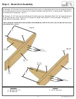
Measure 10-1/2” from tip of one (487) Beam End then place one (485) Beam End 10-1/2 at measured location
on the side without the cut-out, make sure it is square then attach with three #10 x 4” Wood Screws. Repeat for a
second Beam End Assembly. (fig. 4.1)
B:
Measure 10-1/2” from tip of one (487) Beam End then place one (485) Beam End 10-1/2 at measured location
on the side with the cut-out, make sure it is square then attach with three #10 x 4” Wood Screws. Repeat for a
fourth Beam End Assembly. (fig. 4.2)
There should be two Beam End Assemblies with (485) Beam End 10-1/2 on the cut-out side and two on the
side without the cut-out.
Step 4: Beam End Assembly
Hardware
Wood Parts
4 x (485) Beam End 10-1/2
4 x (487) Beam End
12 x #10 x 4” Wood Screw
PG 7
PG 7
Fig. 4.2
#10 x 4”
Wood Screw
Fig. 4.1
(485) Beam
End 10-1/2
(487) Beam
End
Cut-out
Cut-out
#10 x 4”
Wood Screw
(485) Beam
End 10-1/2
(487) Beam
End
10-1/2”
10-1/2”
Flush
Flush


