30
support@yardistrystructures.com
Step 11: Trellis Assembly
Part 4
G:
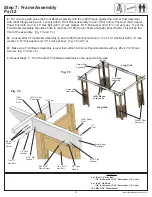
Follow with two Trellis Assembly Bs on each
side of Trellis Assembly A, then Trellis Assembly
C and Trellis Assembly D. Attach each with one
#10 x 1-1/4” Pan Screw per clip. Short and Long
Trellis’ are staggered as shown in fig. 11.3 from
Part 2. (fig. 11.8, 11.9 and 11.10)
Note: The distance between Trellis
Assemblies should be 13-1/2”.
Note that two Trellis Assembly Bs rests on
(026) Splice, the remaining Trellis Assemblies
rest directly on the Front and Inner Beam
Assemblies.
Hardware
64 x #10 x 1-1/4” Pan Screw
Hardware:
72
‐
S12
‐
#10
x
1
‐
1/4"
Pan
Screw
PG 15
Hardware:
72
‐
S12
‐
#10
x
1
‐
1/4"
Pan
Screw
PG 15
Trellis
Assembly B
Front Beam
Assembly
Trellis
Clip
Trellis Clip
(026) Splice
#10 x 1-1/4”
Pan Screw
Trellis
Assembly D
Trellis
Assembly B
Trellis
Assembly C
Trellis
Assembly C
Trellis
Assembly D
Fig. 11.8
Fig. 11.9
Outside View
Fig. 11.10
Inside View
Front Beam
Assembly
Inner
Beam
Assembly
Trellis
Assembly A
Trellis
Assembly D
Trellis
Assembly B
Trellis
Assembly C
Trellis
Assembly C
Trellis
Assembly D
Trellis
Assembly A
Trellis
Assembly B
Front Beam
Assembly
(026) Splice
13-1/2”


