2.
3.
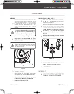
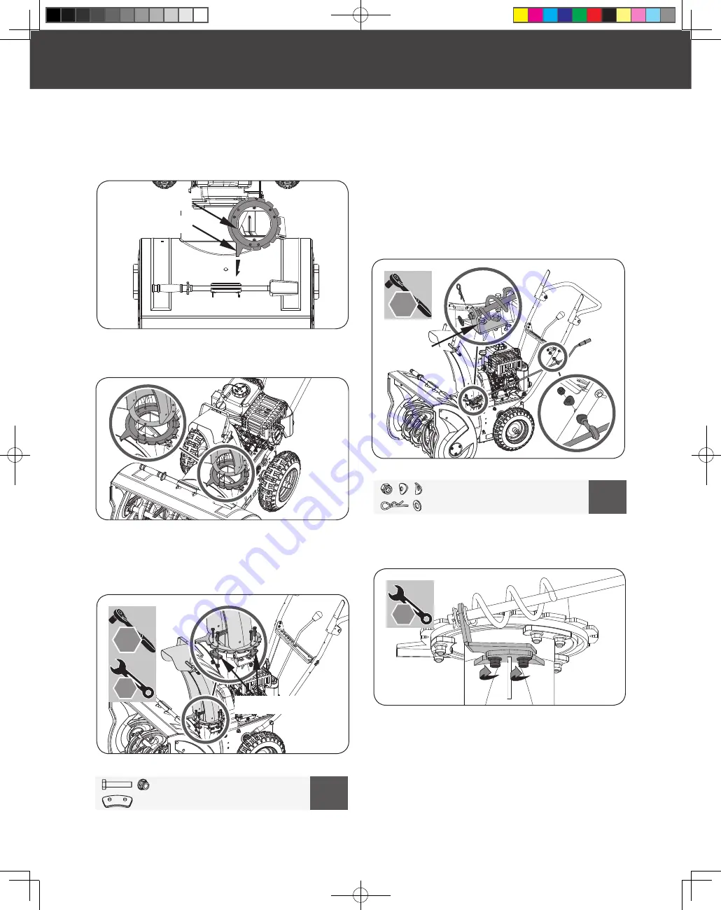
Place the discharge chute facing it forward over the chute
crank flange. (See
Figure 5b
)
Figure 5b
Secure the three flange keepers to the bottom of the chute
crank flange by sliding the bolts through the chute base
holes, sliding the keepers up from the bottom, then securing
them with the included nuts. (See
Figure 5c
)
1.
Sit the chute crank flange on top of the impeller housing.
Make sure the stop triangle points forward so that the
notched edge are on the left side and the pre-greased surface
is on the bottom. (See
Figure 5a
)
Figure 5a
DISCHARGE CHUTE
Chute Crank Flange
Stop Triangle
M6 X 30
X 6
4
X 3
Figure 5c
M8
X 1
5
X 1
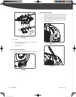
DIRECTIONAL CHUTE CONTROL
1.
2.
3.
Figure 6a
10
mm
13
mm
16
mm
19
mm
Slide the spiral end of the directional chute control lever into
the chute bracket.
Attach the directional chute control lever to the handlebar
through the hole on the left handle by sliding the bolt thru
the hole. Use the curved washer and nut to secure it to the
handlebar. Leave it finger tight for easier alignment later.
Secure the spiral end on the chute bracket by sliding on the
flat washer and clevis pin. (See
Figure 6a
)
Chute Bracket
4.
5.
Figure 6b
Make sure the spiral at the bottom is fully engaging with the
chute crank flange and tighten the two bolts on the chute
bracket. (See
Figure 6b
)
Tighten the nut which secures the directional chute control
on the handlebar.
10
mm
13
mm
18
mm
16
mm
30
mm
32
mm
Flange Keeper
32
mm
10
mm
16
mm
19
mm
10
mm
13
mm
18
mm
16
mm
30
mm
32
mm
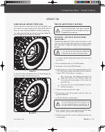
AUGER CLUTCH CABLE AND DRIVE CLUTCH CABLE
Slide the control cables through the holes in the control panel.
Make certain the cables are seated properly in roller guides when
hook the cables to the clutch levers.
10
Two-Stage Snow blower
»
Operator’s Manual
YB6270PM01 - 1708
Assembly
|
30255JUS25M101_GB.indd 10
2017/8/24 19:25:06


