background image

This lawn mower was partially assembled at the factory. To assemble your machine follow the below instructions.

ASSEMBLY

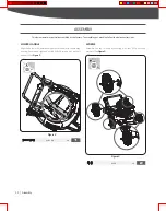
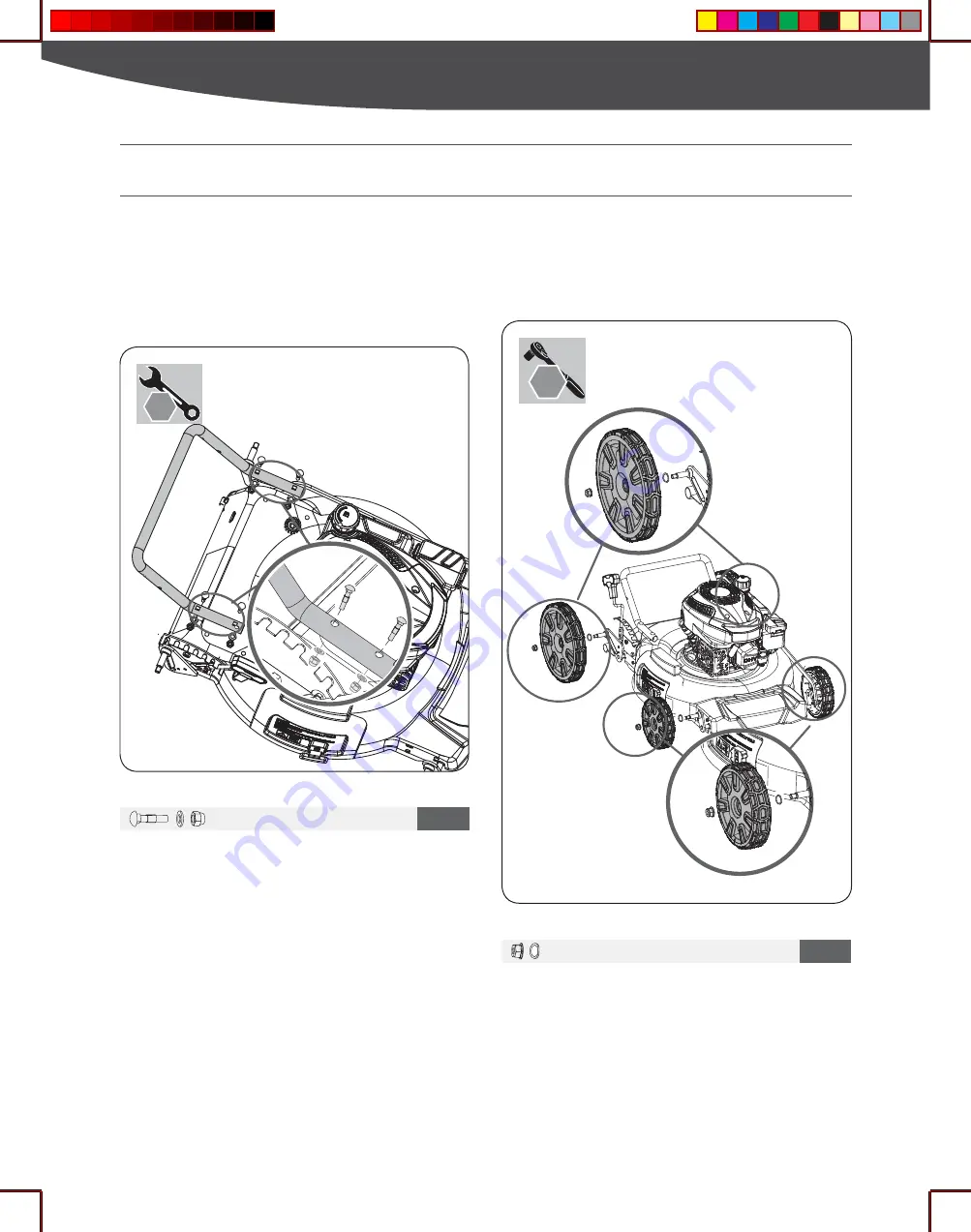
LOWER HANDLE

 Align the holes in the lower handlebar with the holes in the mowing 

housing.  Secure  and  tighten  by  using  M8x40  screws,  flat  washers 

and nuts. (See 

Figure 2

)

WHEELS

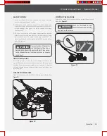
Assemble the four wheels by securing with four M10 nuts and 
washers. (See 

Figure 3

)

Figure 2

Figure 3


M8 × 40

× 4

1


M10

× 4

2

2

13


mm

15


mm

11

|


Assembly

Summary of Contents for YG0545

Page 1: ...umber and serial number may be found on the main labei SeePqe2 Fipre 1 You should record both of them in a safe place for future use A WARNING READ AND UNDERSTAND THE ENTIRE MANUAL BEFORE OPERATING MA...

Page 2: ...ower equipment OPE to get the job done right at the right price YARDMAX delivers the perfect combination of performance and practicality YARDMAX has a solution that s right for you MAX Performance MAX...

Page 3: ...e center A WARNING CALIFORNIA PROPOSITION 65WARNING Engine exhaust some of its constituents and certain product components contain or emit chemicals known to the state of California to cause cancer an...

Page 4: ...3 I Introduction SUPPORT Have questions about your YARDMAX equipment Call us at 847 327 0566 or 844 YARDMAX email us at support yardmax com or contact us via your favorite social media site...

Page 5: ...isplacement 170 cc 170 cc Engine Torque 6 50 ft lb 6 50 ft lb Fuel Tank Capacity 0 21 gallon 0 8L 0 21 gallon 0 8L Oil Capacity 16 9 oz 0 5L 16 9 oz 0 5L Recommended Oil Type SAE 10W 30 SAE 10W 30 Whe...

Page 6: ...arts have stopped before cleaning repairing or inspecting the unit STOP STOP Make sure the engine is off when leaving the mower or not mowing Gasoline and its vapors are extremely flammable and explos...

Page 7: ...dren to operate this machine at any time Only responsible individuals who are familiar with these rules of safe operation should be allowed to use this machine To help avoid blade contact or a thrown...

Page 8: ...ocal or state laws if any WARNING the muffler is missing or defective A defective muffler increases the noise level and the risk of fire Examine the muffler regularly to make sure that it is attached...

Page 9: ...ntrol handle must operate easily in both directions and automatically return to the disengaged position when released Never operate the mower on wet grass Always be sure of your footing A slip and fal...

Page 10: ...us conditions such as slippery surfaces Examine your work area to make sure that your control of the product cannot be prevented Be careful of roots stones twigs pits and ditches High grass can concea...

Page 11: ...el This Operator s Manual covers several models Features may vary by model Not all features in this manual are applicable to all models and the model depicted may differ from yours NOTE 10 Operator s...

Page 12: ...LY LOWER HANDLE Align the holes in the lower handlebar with the holes in the mowing housing Secure and tighten by using M8x40 screws flat washers and nuts See Figure 2 WHEELS Assemble the four wheels...

Page 13: ...cure with wing knobs See Figure 4 UPPER HANDLE Align the holes in the upper handle and the holes in connecting handlebars to set a comfortable height position for the handle then secure and tighten by...

Page 14: ...Use cable tie to secure engine stop cable SIDE DISCHARGE CHUTE 1 Lift the mulch cover on the side of the mower See Figure 7 illustration 1 2 Slide the two hooks of the side discharge cover under hing...

Page 15: ...tart Stop Control Upper Handle Intermediate Connecting Handlebar Lower Handle Recoil Starter Rear Wheel Fuel Cap CuttingHeightAdjustmentLever Side Discharge Chute Mulch Cover Front Wheel 14 Walk Behin...

Page 16: ...squeeze it against the upper handle to operate the unit Release it to stop engine and blade Side Discharge Chute Your mower is shipped as a mulcher To discharge the grass clippings to the side instea...

Page 17: ...ment and or its engine may include evaporative emissions control system components required to meet EPA and or CARB regulations that will only function properly when the fuel tank has been filled to t...

Page 18: ...wn mower Refer to the Engine Operator s Manual for detailed instructions on starting and stopping the engine Adjusting the cutting height may bring you into contact with the moving blade causing serio...

Page 19: ...See Figure 10 Release the engine start stop control lever to stop the engine and blade See Figure 11 SIDE DISCHARGE MODE STOPPING THE MACHINE S TO P 2 1 BLADE CONTROL 1 Standing behind the mower sque...

Page 20: ...check all fasteners and make sure these are tight Clean more often under dusty conditions or when airborne debris is present Replace air cleaner if very dirty 1 Lubricate pivot points on the blade an...

Page 21: ...other debris Follow steps below for proper cleaning 1 Allow the engine to run until it is out of fuel Do not attempt to pour fuel from the engine Disconnect spark plug wire Refer to Engine Operator s...

Page 22: ...vicing the blade WARNING WARNING WARNING BLADE CARE 2 Examine the blade whenever you run out of fuel If the blade is damaged or cracked replace it immediately If the blade edge is dull or nicked have...

Page 23: ...e bolt to see if there is damage Examine the motor shaft to make sure that it is not bent See Figure 17 5 Install the new blade Use a block of wood between the blade and lawn mower housing and tighten...

Page 24: ...and do not store stabilized fuel more than 90 days Apply a coat of chassis grease to mower s cutting blade to prevent rusting Apply a coat of chassis grease to mower s cutting blade to prevent rusting...

Page 25: ...leaner Maintenance in the Engine Manual 6 Contact your Parts Repair Center to have fuel line cleaned Engine overheats 1 Engine oil level low 2 Air flow restricted 1 Fill crankcase with proper oil 2 Cl...

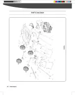
Page 26: ...PARTS DIAGRAM 25 I Parts Diagram...

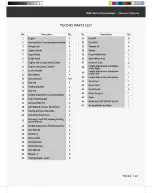
Page 27: ...Left 11 Discontinued N A 40 Height Adjustment Handlebar 1 12 NutM8 4 41 Arm Pivot 1 13 Positioning Bolt 2 42 Rivet4x10 2 14 NutM6 4 43 BoltMSx16 4 15 Height Adjustment Connecting Rod 1 44 Blade Suppo...

Page 28: ...YG1550 18 37 r o Us_ 38 8 E e a t N I...

Page 29: ...Bolt 1 41 Arm Pivot 1 12 Height Adjustment Positioning Plate 1 42 Screw ST3 5 13 2 13 BoltM6x16 2 43 Height Adjustment Handlebar 1 14 Washer6 2 44 Height Adjustment Handlebar 1 Knob Right 15 NutM6 4 H...

Page 30: ...Tame the Great Outdoors YARDMAX Jill 847 327 0566 or 844 YARDMAX I info yardmax com...

Reviews: