background image

model no. 

060-1300-6

  |  contact us: 1.866.523.5218

model no. 

060-1300-6

  |  contact us: 1.866.523.5218

21

Asse

M

bl

y

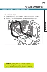
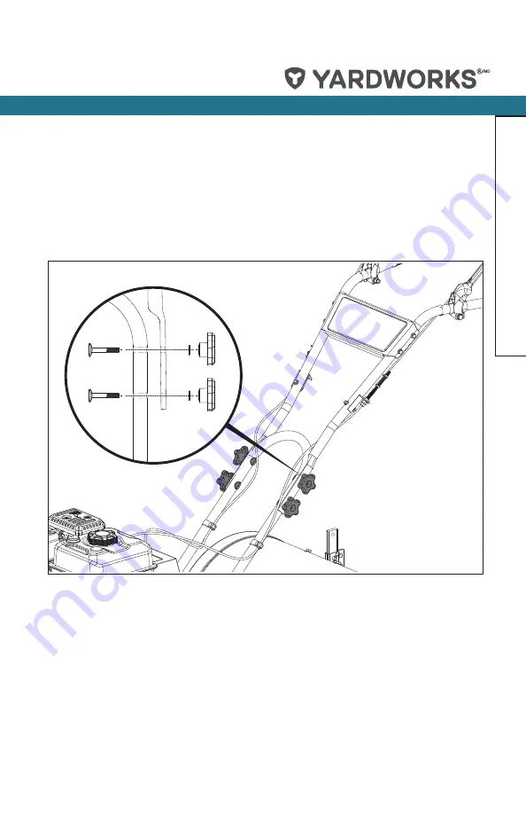
ATTACH UPPeR HANDle
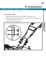
1.  Slide the upper handle down over the lower handle and align the holes. 
2.  Insert the (4) M8×50 curved head bolts into the holes as shown and securely with the 

(4) handle knobs and (4) flat washers. 

3.  Tighten the handle knobs securely. 

Summary of Contents for 060-1300-6

Page 1: ...model number 060 1300 6 contact us 1 866 523 5218 IMPORTANT Read and follow all safety rules and operating instructions before using this product Instruction Manual Rear Tine Tiller...

Page 2: ...ustomer Assistance Please Call 1 866 523 5218 SAFETY INSTRUCTIONS 3 SAFETY SYMBOLS 8 OPERATION SYMBOLS 10 SAFETY LABELS 12 SPECIFICATIONS 14 KNOW YOUR TILLER 15 ASSEMBLY 18 OPERATION 29 TILLING TIPS A...

Page 3: ...stop the unit and disengage the controls quickly Never allow children under age 16 to operate the tiller Never allow adults to operate the tiller without proper instruction Keep the area of operation...

Page 4: ...o vibrate abnormally stop the engine disconnect the spark plug wire and prevent it from touching the spark plug and check immediately for the cause Vibration is generally a warning of trouble Stop the...

Page 5: ...Do not overload the tiller s capacity by attempting to till too deeply at too fast a rate Never operate the tiller at high transport speeds on hard or slippery surfaces Look behind and use care when...

Page 6: ...en Never perform maintenance while the engine is running or the spark plug wire is connected except when specifically instructed to do so If the fuel tank has to be drained do this outdoors FUEL SAFET...

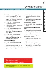
Page 7: ...the gasoline cap air filter spark plug fuel lines and exhaust system are properly in place DANGER GASOLINE AND GASOLINE VAPOURS ARE HIGHLY FLAMMABLE AND EXPLOSIVE Fire or explosion can cause severe b...

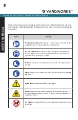
Page 8: ...r safety shoes or heavy boots when operating the machine Gloves Always wear nonslip heavy duty protective gloves when operating this product Safety Alert Precautions that involve your safety Risk of F...

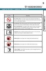
Page 9: ...d other reproductive harm Risk of Asphyxiation This engine emits carbon monoxide an odourless colourless poison gas Breathing carbon monoxide can cause nausea fainting or death Use only in a well vent...

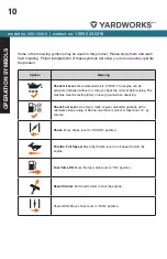
Page 10: ...ded gasoline with a minimum octane rating of 85 and an ethanol content of less than 10 by volume Choke Move choke lever to CHOKE position Throttle Full Speed Move the throttle lever to full speed to s...

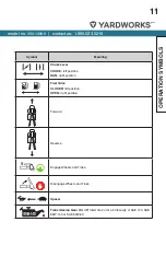
Page 11: ...eaning Choke Lever CHOKE left position RUN right position Fuel Valve CLOSED left position OPEN right position Forward Reverse Engage Wheels and Tines Disengage Wheels and Tines Speed Transmission Gear...

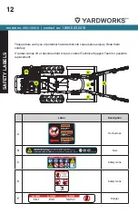
Page 12: ...outside parties without the explicit consent of Champion Power Equipment Fuel C 1253 L SF A DANGER PELIGRO DANGER K 485 2945 109 Colors LPN 1253 L SF Rev A Size 85 x 35 mm Artwork Notes 3mm corner ra...

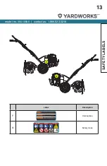
Page 13: ...ut tre n cessaire L utilisateur doit communiquer avec le service d incendie local pour les lois et les r glements relatifs la pr vention des incendies 1047 L SF B K 152 Colors LPN 1047 L SF Rev B Size...

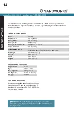
Page 14: ...Fuel Capacity 0 82 gal 3 1 L Oil Capacity 16 9 fl oz 500 ml Oil Type 10W 30 TILLER SPECIFICATIONS ENGINE SPECIFICATIONS FUEL SPECIFICATIONS Use regular unleaded gasoline with a minimum octane rating...

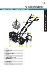
Page 15: ...218 15 Know your Tiller 1 11 2 3 4 5 6 7 8 9 10 1 Front Bumper 2 Wheels 3 Wheel Lock Pins 4 Tines 5 Tine Shield 6 Depth Regulator Lever 7 Reverse Lever 8 Forward Lever 9 Handlebars 10 Speed Control 11...

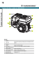
Page 16: ...Throttle 4 Choke Used to start the engine 5 Fuel Valve Used to turn fuel supply on and off to engine 6 Engine On Off Switch 7 Oil Drain Bolt Used to drain the oil 8 Oil Fill Cap Dipstick Used to chec...

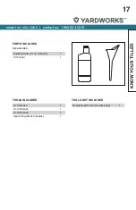
Page 17: ...3 5218 17 Know your Tiller Engine Oil 16 9 fl oz 500 ml 1 Oil Funnel 1 8 10 Wrench 1 12 14 Wrench 1 13 16 Wrench 1 Spark Plug Wrench engine 1 Needle Nose Pliers for cotter pins 1 PARTS INCLUDED Access...

Page 18: ...our Technical Support Team at 1 866 523 5218 Please have your serial number and model number available UNPACKING 1 Remove all parts and packaging components 2 Remove top lid and remove sides 3 Remove...

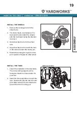
Page 19: ...wheel axle 4 Align the wheel hub hole with the hole in the axle and insert the locking pin 5 Rotate the locking pin ring to lock the pin in position Repeat on other wheel INSTALL THE TINES 1 Check the...

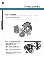
Page 20: ...into the bottom of the depth regulator bracket 3 Insert the pin through the bracket and lever 4 Install the clip removed in 1 onto the depth regulator lever INSTALL THE TINE SHIELD 1 Remove the 4 M10...

Page 21: ...embly ATTACH UPPER HANDLE 1 Slide the upper handle down over the lower handle and align the holes 2 Insert the 4 M8 50 curved head bolts into the holes as shown and securely with the 4 handle knobs an...

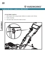
Page 22: ...60 1300 6 contact us 1 866 523 5218 22 Assembly ATTACH SPEED CONTROL 1 Attach speed control using provided 1 M6 bolt 1 washer and 1 M6 nut 2 Tighten completely 3 Use plastic clips to secure the cables...

Page 23: ...he outside of the base frame and align the holes 2 Install the 4 M8 25 mm bolts and 4 M8 lock nuts and tighten securely WARNING Before operating your machine carefully read and understand all safety c...

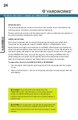
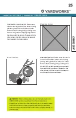
Page 24: ...lever is engaged Use the FREEWHEEL mode only when the engine is not running In FREEWHEEL the wheel locking pins are placed only through the holes in the wheel shaft not the wheel hubs thus allowing t...

Page 25: ...e wheel inward and insert the wheel drive locking pin only through the hole in the axle shaft Secure wheel locking pin by pushing in as far as it will go then wrapping ring around the wheel shaft as s...

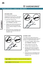
Page 26: ...ge stop the wheels and tines the engine will continue to run REVERSE LEVER The reverse lever controls the reverse motion of the wheels and forward motion of the tines To operate the Reverse Lever 1 Pu...

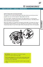
Page 27: ...ing the engine Moving the regulator lever upward will increase the tilling depth The lowest notch allows a tilling depth of approximately 6 15 cm depending on soil conditions For best results always b...

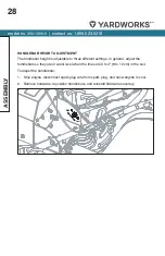
Page 28: ...height is adjustable to three different settings In general adjust the handlebars so they are at waist level when the tines are 3 to 4 8 to 10 cm in the soil To adjust the handlebars 1 Stop engine dis...

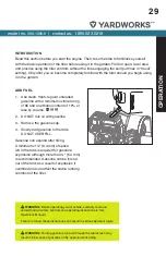
Page 29: ...or less by volume y b c 2 DO NOT mix oil with gasoline 3 Remove the gasoline cap 4 Slowly add gasoline to the tank DO NOT OVERFILL Gasoline can expand after filling A minimum of 6 4 mm of space left...

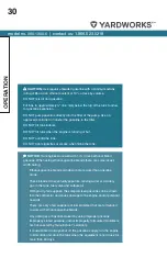
Page 30: ...blend gasoline When using ethanol gasoline blends there are some issues worth noting Ethanol gasoline blends can absorb more water than gasoline alone These blends can eventually separate leaving wat...

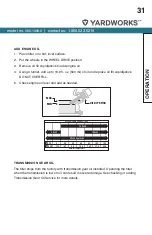
Page 31: ...pstick DO NOT OVERFILL 5 Check engine oil level and add as needed TRANSMISSION GEAR OIL The tiller ships from the factory with transmission gear oil installed Operating the tiller when the transmissio...

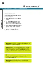
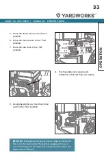
Page 32: ...se all controls on the tiller WARNING Do not attempt to engage the tines or wheels until you have read all of the operating instructions WARNING Before starting engine put both wheels in the WHEEL DRI...

Page 33: ...FUEL ON CHOKE RUN SLOW 8 Pull the starter cord slowly until resistance is felt and then pull rapidly 9 As engine warms up move the choke lever to the Run position RUN NOTICE If the engine starts but d...

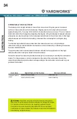
Page 34: ...cting Yardworks Canada 1 866 523 5218 The part number and recommended minimum altitude for the application of the high altitude carburetor main jet is listed in the table below In order to select the...

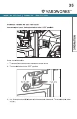
Page 35: ...AND THE TILLER In an emergency turn the engine switch to the OFF position Under normal operation 1 To stop the wheels and tines release all control levers 2 Turn the fuel valve to the OFF position 3 L...

Page 36: ...ultivating breaking up surface soil around plants to destroy weeds adjust the tines to dig only 1 to 2 2 5 to 5 cm deep Using shallow tilling depths helps prevent injury to plants whose roots often gr...

Page 37: ...g Test soil by squeezing it into a ball If it compresses too easily it is too wet to till PREPARING SEEDBEDS When preparing a seedbed go over the same path twice in the first row then overlap one half...

Page 38: ...rganic matter to the soil so that it has good moisture holding texture and try to avoid leaving footprints or wheel marks When tilling vertically try to make the first pass uphill as the tiller digs m...

Page 39: ...3 60 to 90 cm feet wide Digging too far into the side of the slope will expose poor subsoil that is unproductive for plants To create a terrace start at the top of the slope and work down Go back and...

Page 40: ...hile power composting try swaying the handlebars from side to side about 6 to 12 15 to 30 cm This fishtailing action often clears the tines of debris If tangling occurs lift the tines out of the soil...

Page 41: ...the better Turn the vehicle s engine off and apply its parking brake When going up ramps stand in the normal operating position and push the tiller ahead of you Have a person at each side to turn the...

Page 42: ...ours Clean up carbon from cylinder head piston Every 10 Operating Hours Check drive belt tension Check nuts and bolts Change engine oil Lubricate tiller Every First Month or First 20 Hours Change engi...

Page 43: ...he threads on the handlebar height adjustment screws and the handlebar attaching screws CHECK FOR OIL LEAKS Before each use check the tiller for signs of an oil leak usually a dirty oily accumulation...

Page 44: ...TRANSMISSION GEAR OIL SERVICE Check the transmission gear oil level after every 30 hours of operation or whenever you notice any oil leak Operating the tiller when the transmission is low on oil can...

Page 45: ...Gear Oil The transmission gear oil does not need to be changed unless it has been contaminated with dirt sand or metal particles 1 Drain gasoline from the fuel tank or run the engine until the fuel t...

Page 46: ...ome shorter narrower and pointed Badly worn tines will result in a loss of tilling depth and reduced effectiveness when chopping up and turning under organic matter B Removing Installing a Single Tine...

Page 47: ...re the tine assembly to the tine shaft If necessary use a rubber mallet to tap the tine assembly outward off the shaft 3 Before reinstalling the tine assembly inspect the tine shaft for rust rough spo...

Page 48: ...n check the belt for cracks cuts or frayed edges and replace it as soon as possible To Check Belt Tension 1 Stop engine wait for all parts to stop moving and disconnect spark plug wire 2 With the forw...

Page 49: ...o the lever 5e Repeat Steps 2 and 3 to re measure the length of the spring When the second measurement is between 1 16 to 3 16 2 to 5 mm shorter than the first measurement re tighten the hex nut again...

Page 50: ...reafter check tension after every 2 hours of operation To increase belt tension 1 Turn jam nut clockwise in 1 8 3 mm increments 2 Check adjustment To decrease belt tension 1 Turn jam nut counter clock...

Page 51: ...rom spark plug 3 Reduce the belt tension by loosening the forward and reverse cable lower jam nut 4 Remove the upper and lower belt guards 5 To remove the reverse drive belt 5a Remove the reverse belt...

Page 52: ...ard drive belt 6a Remove the two forward belt guide studs and forward belt idler assembly Forward Belt Idler Forward Stud Assembly 6b Slide the belt free of the engine pulley 6c Pull the belt down and...

Page 53: ...the reverse belt idler 7b Place the lower loop of the belt around the rear portion of the transmission pulley 7c Replace the reverse belt idler into the reverse belt idler bracket The belt should not...

Page 54: ...erneath the unit and up around the rearward portion on the engine pulley 8b Place the lower loop of the belt around the rearward portion of the transmission pulley 8c Replace the forward belt guide st...

Page 55: ...start the engine and operate the forward drive lever to check for proper cable adjustment and belt tension See the Belt Tension Adjustment section if cable adjustment is required 14 Start the engine a...

Page 56: ...ual for air cleaner service intervals and instructions ENGINE OIL SERVICE Check the engine oil level before each use and after every five hours of continuous operation Running the engine when it is lo...

Page 57: ...einstall the wheel 9 Refill the with engine oil through the dipstick with funnel and replenish the fuel tank with gasoline DRAIN BOLT CAUTION DO NOT attempt to crank or start the engine before it has...

Page 58: ...eat piston rings Avoid bogging or lugging the engine down and avoid prolonged running at constant RPM After the 5 hour break in period change the oil Using synthetic oil does not increase the recommen...

Page 59: ...ke when starting 3 Clean the air cleaner cover and inner surface with a damp cloth Be careful not to allow the dust to enter the carburetor 4 Reinstall the element and reinstall the air cleaner cover...

Page 60: ...nd 7 Screw in the spark plug first by hand then use a spark plug wrench to compress the gasket 7a If a new spark plug is used twist another 1 2 turn after compressing the gasket 7b If reinstalling a u...

Page 61: ...into the cylinder Crank the engine to distribute engine oil evenly 7 Reinstall the spark plug 8 Store unit in a clean dry area 9 Never store the tiller with fuel in the fuel tank in an enclosed area w...

Page 62: ...e used gasoline and add fresh gasoline 2 Months to a Year Drain the used gasoline and add fresh gasoline Drain the gasoline out of the carburetor cup Drain the gasoline out of the sediment bowl Over a...

Page 63: ...model no 060 1300 6 contact us 1 866 523 5218 63 PAGE INTENTIONALLY LEFT BLANK...

Page 64: ...model no 060 1300 6 contact us 1 866 523 5218 model no 060 1300 6 contact us 1 866 523 5218 64 EXPLODED VIEW PRODUCT EXPLODED VIEW PRODUCT...

Page 65: ...model no 060 1300 6 contact us 1 866 523 5218 65 EXPLODED VIEW PRODUCT...

Page 66: ...model no 060 1300 6 contact us 1 866 523 5218 66 EXPLODED VIEW PRODUCT...

Page 67: ...model no 060 1300 6 contact us 1 866 523 5218 67 EXPLODED VIEW PRODUCT...

Page 68: ...08 2 2 12 Flat Washer 6 100379 019 3 13 Locknut M6 100379 020 3 14 Flange Locknut M6 100379 099 2 15 Clutch Rod 100380 009 2 16 Locknut M5 100380 010 2 17 Pull Pole Protector 100380 011 2 18 Flat Wash...

Page 69: ...t Buckle 100380 029 1 42 Reverse Tension Sleeve 100380 030 1 43 Reverse Tension Wheel 100380 031 1 44 Belt 5PK730 100380 115 1 45 Bearing 6200 100380 033 3 46 Circlip 30 100380 034 2 47 Spring Washer...

Page 70: ...00380 052 1 72 Tension Wheel 100380 053 1 73 Retaining Stem Components Belt 100380 054 1 74 Belt Block Set 2 100380 055 1 75 Tension Wheel Pole 100380 056 1 76 Belt Block Set 1 100380 057 1 77 Spring...

Page 71: ...80 077 1 103 Big Belt Wheel 100380 078 1 104 Screw M6 x 20 100379 005 3 105 Small Belt Cover Protector Assembly Cool Gray 100380 079 29 1 106 Front Cover Black 100380 080 2 1 107 Framework Oil Seal 20...

Page 72: ...100380 105 2 1 131 Box Black 100380 106 2 1 132 Rivet 100379 013 1 133 Saddle Elastic Washer 10 100379 123 1 134 Plug 100379 122 2 135 Accelerator Components In Hand Black 100379 112 1 1 136 Throttle...

Page 73: ...model no 060 1300 6 contact us 1 866 523 5218 73 PAGE INTENTIONALLY LEFT BLANK...

Page 74: ...9 10 11 12 13 14 15 16 17 18 19 20 21 23 24 22 25 26 27 28 29 29 30 31 32 33 33 34 35 36 37 38 39 40 41 41 42 43 44 45 46 47 47 47 47 47 48 49 50 51 52 53 54 55 56 57 58 59 60 61 62 63 64 65 66 67 68...

Page 75: ...M8 x 60 Blue White Zinc 12003 Z010110 0000 4 11 Valve Lock Clamp 12109 Z810110 0000 4 12 Valve Spring Retainer 12112 Z810210 0000 2 13 Valve Spring 12103 Z010110 0000 2 14 Seal Guide 12101 Z810210 00...

Page 76: ...te Zinc 16070 Z010110 0000 1 41 Hexagon Flange Nut M6 Blue White Zinc 90305 0600 31 3 42 Governor Support Bolt M6 x 21 Blue White Zinc 16072 Z010110 0000 1 43 Spring Governor 16063 Z050710 0000 1 44 G...

Page 77: ...ne Switch Subassembly 35540 Z010610 R901 1 70 Recoil Starter Assembly 28200 Z141010 HL01 1 71 Washer Black Zinc 90408 0600 03 3 72 Hexagon Flange Bolt M6 x 8 Black Zinc 90001 0608 03 3 73 Clip 90684 Z...

Page 78: ...0000 1 91 Fuel Tank 16620 Z810110 HL01 1 92 Fuel Tank Oil Outlet Subassembly 16680 Z010110 0001 1 93 Clamp 90740 Z010510 00A0 2 94 Fuel Pipe 4 5 x 8 5 x 160 90686 Z010710 0001 1 95 Rubber Jacket 9 5 x...

Page 79: ...ut of adjustment Contact Technical Support Team Stale gasoline Replace with fresh gasoline Dirt or water in fuel tank Contact Technical Support Team Engine cooling system clogged Clean air cooling sys...

Page 80: ...on Adjustment DIFFICULTY STARTING ENGINE RECOIL PROBLEM POSSIBLE CAUSE SOLUTION Something wrong with the fuel system fuel supply is not smooth or no fuel supply There is no enough fuel in fuel tank an...

Page 81: ...ket is missing Tighten with a gasket in Air leakage between cylinder block and cylinder head Check cylinder gasket and the flatness of the surface where the cylinder block contacts the cylinder head T...

Page 82: ...le and main oil flow hole clogged Clean and blow to clear Fuel cock is clogged up Clean replace damaged part Too much carbon deposit in combustion chamber Clear away Too much carbon fouling in muffler...

Page 83: ...pin and piston pin hole are worn excessively Replace tie rod Roller bearing for crankshaft main shaft is worn Replace roller bearing Abnormal combustion Engine is too hot Shut down and allow engine t...

Page 84: ...ogged Check fuel line and dredge Float is leaking Repair Needle valve is stuck Dismantle float chamber and eliminate Spark plug is punctured or short circuited by carbon deposit Replace spark plug Ele...

Page 85: ...worn to make a space between cylinder and crankcase Replace the worn parts Crankshaft main bearing burned out Replace main bearing Beating sound Piston piston ring or cylinder is worn Replace the worn...

Page 86: ...in material and workmanship for a period of one hundred twenty 120 days from the date of retail purchase HOW TO OBTAIN SERVICE Warranty service is available by calling the toll free helpline at 1 866...

Reviews: