background image


11 


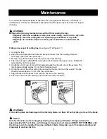
Edging 

(

See Figure 12 & Figure 13.)


For edging, push the button and rotate the handle. The handle will rotate to 90°, 180° position, while 
releasing the button. When the hand is in position, the button will lock into place. The hand will only rotate in 
one direction. Do not use the heavy duty cutting system for edging. 


3-position adjustment 

(

See Figure 14.)


1. Push the yellow button 
2. Adjust handle to the desired angle 
3. Release the button. The handle locks in position. 


Secure the power cable 

(

See Figure 15.)


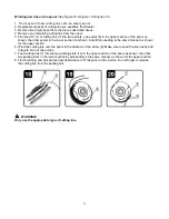
Form a loop in the end of the extension cable, conduct it through the opening in the upper handle and hang 
it on to the strain relief. 


Summary of Contents for 060-2279-2

Page 1: ...ELECTRIC GRASS TRIMMER EDGER 060 2279 2 Owner s Manual Toll free helpline 1 866 523 5218 Read all safety rules and instructions carefully before operating this tool...

Page 2: ...ing path 14 35 cm Cutting Line Length 2 4 m Weight 5 5 lbs 2 5 kg Spool line 60 2269 6 Contents Contents Specifications Warranty General Safety Rules Electrical Information Know Your String Trimmer As...

Page 3: ...in material and workmanship for a period of one hundred twenty 120 days from the date of retail purchase How to Obtain Service Warranty service is available by calling the toll free helpline at 1 866...

Page 4: ...n off the device while people especially children or pets are nearby Only use the device in daylight or good artificial light Before using the device and after any impact check for signs of wear or da...

Page 5: ...ance Read the instructions carefully Be familiar with the controls and proper use of the equipment Before use check the power and extension cords for signs of damage or wear If the cord is damaged dur...

Page 6: ...roperly wired and in good electrical condition Always replace a damaged extension cord or have it repaired by a qualified person before use Keep extension cords away from sharp objects excessive heat...

Page 7: ...use of this product requires an understanding of the information on the product and in this operator s manual as well as a knowledge of the project you are attempting Before use of this product famil...

Page 8: ...the position of figure 3 Secure the guard with the screw WARNING Never use the tool unless the guard is properly fitted Fitting the secondary handle See Figure 4 Figure 5 1 Place the handle on the to...

Page 9: ...locks into place WARNING Never attempt to lock the trigger lever in the on position Hint for optimum use See Figure 8 In order to achieve optimum cutting results only cut dry grass Trimming 1 Hold the...

Page 10: ...the line length manually See Figure 11 Disconnect the plug from the mains socket Press the retaining head B release it again and pull the ends of the cord out a little Repeat this process until the e...

Page 11: ...The hand will only rotate in one direction Do not use the heavy duty cutting system for edging 3 position adjustment See Figure 14 1 Push the yellow button 2 Adjust handle to the desired angle 3 Relea...

Page 12: ...60 2269 6 and push it into the boss in the spool cover Rotate the spool slightly until it is seated 5 Unclip the end of one of the cutting lines and guide the line into one of the eyelets The line sh...

Page 13: ...ection not shown but still proceeding in the same manner as shown for the upper section 6 Wind the cutting line onto the spool in the direction of the arrow 9 Make sure to wind the line neatly and in...

Page 14: ...ll the cutting line until it protrudes 11cm from the housing If insufficient cutting line is left on the spool install a new spool of cutting line as instructed above Align the tabs on the spool cover...

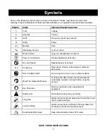
Page 15: ...speed at no load min Per Minute Revolutions strokes surface speed orbits etc per minute Wet Conditions Alert Do not expose to rain or use in damp locations Read The Operator s Manual To reduce the ris...

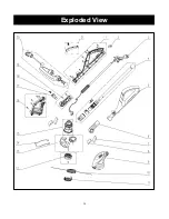
Page 16: ...16 Exploded View...
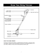
Page 17: ...left motor shell 1 10 GT15FM 20 20 spool line 1 11 GT15FM 20 01 spool cover 1 12 GT15FM A0 04 spool assembly 1 13 GT15FM A0 03 safety guard assembly 1 14 GT01FM 00 11 spacer guard 1 15 TM65XX 00 00 mo...

Reviews: