background image

model no. 

060-2385-8

  |  contact us: 1.866.523.5218

model no. 

060-2385-8

  |  contact us: 1.866.523.5218

41

PARTS

 LIS

T–

C

 (PRODUC

T)

Item

Description

Drawing

QTY.

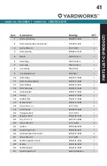
1

Starter Assembly

F28.0210.0000

1

2

Start Housing Decorative Board

F28.0210.0001

1

3

Screw M5 x 20

01.01.6201

3

4

Start Housing

F28.0210.0100

1

5

Eyelet

YD25.02.01-2

1

6

Start Rope

YD25.02.00-5

1

7

Start Grip

YD62.02.00-3

1

8

Coil Spring

YD42.06-6

1

9

Coil Spring Cover

YD42.06-7

1

10

Start Pulley

F28.0110.0009

1

11

Start Torsional Spring

F28.0110.0002

1

12

Start Ratchet

F28.0110.0001

1

13

Start Dial Claw

F28.0110.0003

2

14

Plate Washer

F28.0110.0004

1

15

Circlip

F28.0110.0005

1

16

Rubber Pad

F28.0110.0008

1

17

Muffler Cover

F28.0110.0006

1

18

Screw ST4 × 10

01.01.3131

5

19

Air Deflector

F28.0210.0002

1

20

Flange Nut M8

01.01.0073

1

21

Magneto Rotor

F28.0106.0100

1

22

Key 3 x 5 x 13

A45.0101.0036

1

23

Screw M4 x 20

01.01.6208

2

24

Ignition

F28.0106.0200

1

25

Spark Plug Cover

F28.0106.0201

1

26

Heat Insulation Pad, Stator

F28.0101.0005

2

27

Screw M5 x 60

01.01.6234

2

28

Muffler Insulation Cover

F28.0101.0004

1

29

Muffler

F28.0105.0000

1

30

Muffler Gasket

F28.0101.0003

1

31

Spark Plug RCJ7Y

A45.0106.0500-2

1

Summary of Contents for 060-2385-8

Page 1: ...serious injury This manual should remain with the product Specifications descriptions and illustrations in this manual are as accurate as known at the time of publication but are subject to change wi...

Page 2: ...u For Customer Assistance Please Call 1 866 523 5218 SAFETY INSTRUCTIONS 3 SAFETY SYMBOLS 7 OPERATION SYMBOLS 9 SPECIFICATIONS 11 SAFETY LABELS 12 CONTROLS AND FEATURES 14 ASSEMBLY 15 OPERATION 20 MAI...

Page 3: ...with ANSI Z87 1 along with hearing protection Failure to do so could result in objects being thrown into your eyes and other possible serious injuries Keep all bystanders children and pets at least 5...

Page 4: ...blower tubes Use only as directed in this operator s manual SAFETY INSTRUCTIONS Do not operate vacuum without vacuum bag installed flying debris could cause serious injury Always close vacuum bag comp...

Page 5: ...numbness pain loss of strength change in skin color or texture or loss of feeling in the fingers hands or joints discontinue use of the tool and seek medical attention For such use it may be appropri...

Page 6: ...a vehicle When draining the fuel tank use an approved fuel storage container in a well ventilated area Select bare ground stop engine and allow to cool before refueling Save these instructions Refer...

Page 7: ...Fire can cause severe burns or death Do not add fuel while the product is operating or still hot Open Flame Alert Fuel and its vapours are extremely flammable and explosive Keep fuel away from smoking...

Page 8: ...ntact with any hot surface Rotating Impeller To avoid severe damage to the impeller do not vacuum metal broken glass or similar items Rotating Impeller Keep clear of blower outlet Never point the blow...

Page 9: ...See Starting and Stopping Section Engine START To start the engine follow the starting instructions The switch is always in the START position unless depressed Engine STOP To stop the engine depress...

Page 10: ...es pre mixing gasoline and 2 cycle oil Thoroughly mix the proper ratio of 2 cycle engine oil with unleaded gasoline in a separate fuel can See Fueling and Refueling section 40 1 fuel oil ratio Do not...

Page 11: ...VAC SPECIFICATIONS SPARK PLUGS FUEL MIXTURE This product is powered by a 2 cycle engine and requires pre mixing gasoline and 2 cycle oil in a 40 1 ratio Pre mix unleaded gasoline and 2 cycle engine oi...

Page 12: ...t the explicit consent of Champion Power Equipment Hot Surface B CG11 109 2945 483 Colors LPN 1373 L SF Rev A Size 48 x 18 mm Artwork Notes 2mm safe margin white to be printed shown in 50 process mage...

Page 13: ...Artwork Notes 2mm safe margin white to be printed shown in 50 process magenta Revision Changes This artwork belongs to Champion Power Equipment The contents are confidential and privileged and shall n...

Page 14: ...acuum handle E Fuel cap F Starter grip G Primer bulb H Upper handle I Throttle trigger J STOP switch K Throttle lock Choke not shown behind starter grip L Upper vacuum tube M Tube lock N Lower vacuum...

Page 15: ...n serious personal injury WARNING If any parts are damaged or missing do not operate this product until the parts are replaced Use of the product with damaged or missing parts could result in possible...

Page 16: ...lower blower tubes at the arrows Once confirmed all 4 arms fit flush together press the two parts together 2 Insert screws and tighten completely on all 4 sides 3 Align the raised tabs on the blower t...

Page 17: ...ss the tab to release the blower 2 Slightly twist the blower tube until it releases from the blower outlet 3 Remove the blower tube from the blower outlet 4 Align the slots of the vacuum bag adaptor w...

Page 18: ...ose the inlet with the hook and loop fastener provided 6 Secure the upper and lower vacuum tubes together by aligning the arrows 7 Push together as far as possible until they lock in place 8 Insert a...

Page 19: ...0 While holding the impeller door open align the slots on the vacuum tube with the tabs in the impeller intake 11 Insert the upper vacuum tube into the impeller intake 12 Twist the upper vacuum tube c...

Page 20: ...volume DO NOT USE E15 or E85 Recommended oil Use premium 2 cycle oil or an equivalent high quality synthetic 2 cycle oil Do not use automotive oil or 2 cycle outboard oil Gasoline US gal Oil oz 1 0 3...

Page 21: ...oxygenated fuel blend containing more than the percentages of oxygenates previously stated are not covered under warranty Filling the Tank 1 Place the blower vacuum on a flat stable surface with the f...

Page 22: ...til engine runs Do not pull the starter grip more than four 4 times 7 When the engine has started press and release the throttle trigger E a few times and allow the engine to idle and warm up NOTICE T...

Page 23: ...e knob C to the RUN position 2 Slowly press the primer bulb D 4 6 times 3 Pull the starter grip A until the engine runs 4 When the engine has started press and release the throttle trigger E To Stop T...

Page 24: ...ildren pets open windows or freshly washed cars and blow debris safely away Operation Check your equipment before operation especially the muffler air intakes and air filters Install the blower tube R...

Page 25: ...Comply with the times listed in local ordinances WARNING Never run the unit without the blower tubes installed or the vacuum door securely closed Use of an improperly assembled unit could result in s...

Page 26: ...the impeller do not vacuum metal broken glass or similar items Operation Install the vacuum tubes and the bag Refer to the ASSEMBLY section earlier in this manual Start the blower Refer to Starting an...

Page 27: ...ng and disconnect the spark plug wire before cleaning out the obstruction Remove the vacuum tubes and clear the debris from the blower fan housing Remove the bag and clear the tube A small rod or stic...

Page 28: ...these instructions can result in serious personal injury or property damage WARNING When servicing use only identical replacement parts Use of any other parts could create a hazard or cause product d...

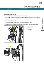
Page 29: ...an Remove the air filter cover by turning the dial counter clockwise while gently pulling on the cover Rinse filter with clean water Gently squeeze filter until excess water is removed Replace filter...

Page 30: ...or loose fasteners any damage or corrosion or blockage caused by insect nests If any sign of exhaust leakage is found stop using the machine and have it repaired immediately VACUUM BAG A dirty bag wil...

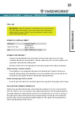
Page 31: ...uel from tank into a container approved for gasoline Run engine until it stops HIGH ALTITUDE ENGINE OPERATION Please have an authorized service centre adjust this engine if it is to be run above 2000...

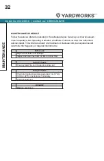
Page 32: ...ce dealer Time intervals shown are maximum Actual use and your experience will determine the frequency of required maintenance Before use Wipe off fuel leaks fuel spillage Inspect and clean fuel tank...

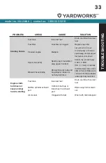
Page 33: ...plug is fouled wet plug gap is incorrect Clean dry correct gap 0 024 0 028 0 6 0 7 mm or replace Blower Vacuum tube Blower Vacuum tube and bag adaptor tubes are not fully installed Install blower tub...

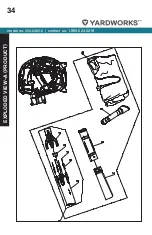
Page 34: ...model no 060 2385 8 contact us 1 866 523 5218 34 EXPLODED VIEW A PRODUCT...

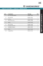
Page 35: ...e Assembly F28 0414 0000 1 2 Fore Air Tube F28 0414 0001 1 3 Bushing F28 0414 0003 4 4 Screw ST4 9 x 115 F28 0414 0005 4 5 Sleeve F28 0414 0004 1 6 Rear Air Tube F28 0414 0002 1 7 Aspiration Channel 2...

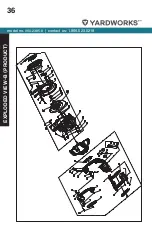
Page 36: ...model no 060 2385 8 contact us 1 866 523 5218 36 EXPLODED VIEW B PRODUCT...

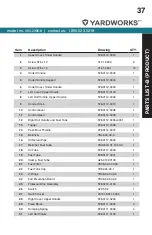
Page 37: ...9 1 12 Right Half Handle and Fuel Tank F28 0112 0005 0001 1 13 Trigger F28 0112 0006 1 14 Push Rod Throttle F28 0112 0007 1 15 Balancer YD45 03 00 5 1 16 Oil Return Pipe F28 0117 0002 1 17 Retainer Fu...

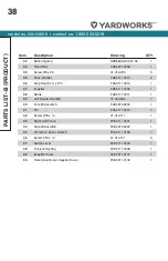
Page 38: ...mpeller F28 0111 0009 1 38 Blade F28 0111 0011 1 39 Left Handed Nut M8 01 03 0284 1 40 Fore Microswitch F28 0213 0200 1 41 Pin F28 0111 0012 4 42 Screw ST5 x 14 01 01 4111 1 43 Right Half Volute F28 0...

Page 39: ...model no 060 2385 8 contact us 1 866 523 5218 39 This page intentionally left blank...

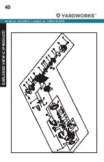
Page 40: ...model no 060 2385 8 contact us 1 866 523 5218 40 EXPLODED VIEW C PRODUCT...

Page 41: ...Start Ratchet F28 0110 0001 1 13 Start Dial Claw F28 0110 0003 2 14 Plate Washer F28 0110 0004 1 15 Circlip F28 0110 0005 1 16 Rubber Pad F28 0110 0008 1 17 Muffler Cover F28 0110 0006 1 18 Screw ST4...

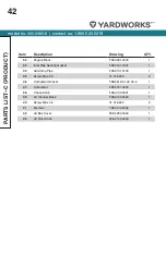
Page 42: ...1 1 34 Admitting Pipe F28 0101 0100 1 35 Screw M5 x 25 01 01 6203 2 36 Carburetor Gasket TBC261D 01 00 00 4 1 37 Carburetor F28 0101 0200 1 38 Choke Knob F28 0100 0001 1 39 Air Cleaner Base F28 0104 0...

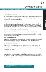
Page 43: ...free from defects in material and workmanship for a period of one hundred twenty 120 days from the date of retail purchase HOW TO OBTAIN SERVICE Warranty service is available by calling the toll free...

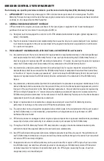
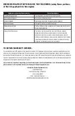
Page 44: ...ER S EMISSION CONTROL SYSTEM WARRANTY COVERAGE This emission control system is warranted for two years subject to provisions set forth below If during the warranty period emission related part on your...

Page 45: ...e warranted for the remainder of the ECS Warranty Period 3c Any warranted emissions related part which is scheduled for replacement as required maintenance in the Owner s Manual shall be warranted for...

Page 46: ...por separator carbon canister canister mounting brackets carburetor purge port connector TO OBTAIN WARRANTY SERVICE You must take your CPE engine or the product on which it is installed along with you...

Reviews: