background image

9

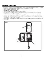
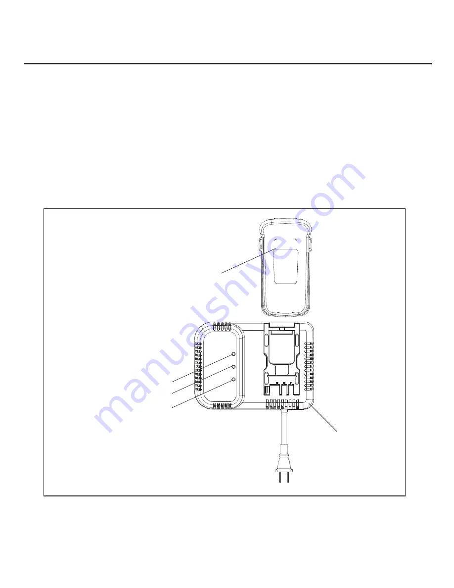
Fig. B

1

2

3

4

5

With regular use,  the battery pack will need 90 MINUTES or less to fully charge.  Allow the battery to fully discharge before 

recharging.  It is recommended to charge the battery pack every 3 months when not in use.

1. Plug the charger 

(5)

 into an AC power outlet.

2. Insert the battery pack 

(4)

 into the charge

r.

    Make sure the latch and battery are fully inserted into the charger.

3. Wait 5 seconds, the LED light 

(1)

 will turn on, indicating a connection to the power source and that the battery is 

    charging, as long as the charger is not plugged in.

4. When the battery has become fully charged, the green LED 

(2)

 light will turn on. The battery can be stored in the 

    charger

, as long as the charger is not plugged in.

5. If the amber LED light 

(3)

 comes on, it is recommended to remove the battery pack and allow the battery to cool for 

    30 minutes. If the amber light remains on once the battery has cooled and has been reinserted in the charger, call the 

    toll-free helpline at 1-866-523-5218 for assistance.

6. NOTE: If both amber and green lights illuminate, keep battery in charger for approximately 30 minutes and battery will 

    start charging.

CHARGING PROCEDURE


Summary of Contents for 60-2273-4

Page 1: ...60 2273 4 Owner s Manual WARNING Read and follow all safety rules and operating instructions before using this product TOLL FREE HELPLINE 1 866 523 5218 CORDLESS GRASS TRIMMER EDGER...

Page 2: ...CTIONS 14 WARRANTY EXPLODED VIEW 24 MAINTENANCE 22 PARTS LIST 25 23 Motor 24V Battery 24V 1 7Ah nickel cadmium Feed Automatic Speed 8000 RPM no load Cutting Path 12 30 cm Line diameter 0 065 1 65 mm C...

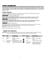
Page 3: ...al information Safety Tool Symbols IMPORTANT Some of the following symbols may be used on your tool Please study them and learn their meaning Proper interpretation of these symbols will allow you to o...

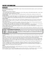
Page 4: ...proper footing and balance at all times Proper footing and balance enable better control of the tool in unexpected situations Tool Use and Care Do not use tool if switch does not turn it on or off A t...

Page 5: ...he tool while people especially children or pets are nearby Keep the cutting head and motor clean to reduce the risk of injury Use only the specified size and type of cutting line Do not substitute Fo...

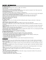
Page 6: ...s wider than the other This plug will fit into a polarized outlet only one way If the plug does not fit fully in the outlet reverse the plug If it still does not fit contact a qualified electrician to...

Page 7: ...rass trimmer and battery charger If any parts are missing or damaged please call 1 866 523 5218 for assistance To reduce the risk of fire electric shock and personal injury Read all instructions befor...

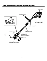
Page 8: ...ck Trigger switch Auxiliary handle Auxiliary handle adjustment knob Pivoting head adjustment button Edge Guide Motor housing Guard Single line cutting spool KNOW YOUR 24 V CORDLESS GRASS TRIMMER EDGER...

Page 9: ...ce and that the battery is charging as long as the charger is not plugged in 4 When the battery has become fully charged the green LED 2 light will turn on The battery can be stored in the charger as...

Page 10: ...TRUCTIONS Battery pack Fig C To avoid injury and to reduce the risk of electric shock or fire Replace the battery pack or charger immediately if the battery case or charger cord is damaged Always make...

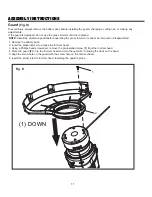
Page 11: ...nnot be removed or disassembled 1 Remove the battery pack 2 Invert the grass trimmer to access the trimmer head 3 Using a Phillips head screwdriver remove the pre installed screw 1 from the trimmer he...

Page 12: ...iliary handle adjustment knob 1 counter clockwise several turns to loosen the auxiliary handle 2 2 Adjust the handle position to provide the best level of balance and control for the operator 3 Secure...

Page 13: ...pre wound spool 2 Insert the end of line through the opening 4 in the spool housing 3 3 Align the tabs on the spool cover with the slots in the spool housing on the trimmer head 4 Push down on the spo...

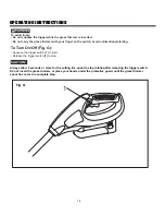
Page 14: ...ional starting To Turn On Off Fig G Squeeze the trigger switch 1 to start Release the trigger switch 1 to stop WARNING Always allow 5 seconds or more for the cutting line spool to stop rotating after...

Page 15: ...alkways patios and or driveways to clear over grown grass from manicured surfaces Fig H PULL UP EDGING COUPLER TO ROTATE REAR HANDLE EDGER GUIDE 1 Pull up edging coupler and turn handle end counterclo...

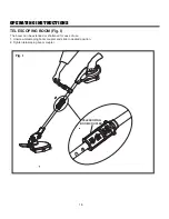
Page 16: ...G INSTRUCTIONS Fig I TELESCOPING BOOM The boom can be extended or shortened for ease of use 1 Unscrew telescoping boom coupler and slide to desired position 2 Tighten telescoping boom coupler TELESCOP...

Page 17: ...voting head 1 Using your left hand grip the nose 1 of the trimmer and use your thumb to depress the pivoting head adjustment button 2 Using your right hand turn the head to either of the 3 available p...

Page 18: ...nt which automatically feeds additional line to the correct length as it wears down If the line does not automatically advance the trimmer line may be tangled or empty To replace the spool see Page 13...

Page 19: ...sible guide the grass trimmer to the left to cut The line will cut as soon as it leaves the guard and the clippings are thrown away from you To produce a smoothly trimmed area move the grass trimmer i...

Page 20: ...ed by debris or foreign material If the surrounding air temperature is not normal room temperature move the charger and battery pack to a location where the temperature is between 65 and 75 F 18 and 2...

Page 21: ...ws not supplied 2 Locate the placement for the charger to be wall mounted 3 If fastening to wood studs use 2 wood screws 4 Drill two holes 4 7 8 12 4 cm on centre ensuring they are level 5 If fastenin...

Page 22: ...rgents on the plastic housing or plastic components Certain household cleaners may cause damage and may also cause a shock hazard Lubrication No lubrication is needed The following toxic and corrosive...

Page 23: ...nal purchaser to be free from defects in material and workmanship for a period of one hundred twenty 120 days from the date of retail purchase How to Obtain Service Warranty service is available by ca...

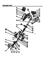
Page 24: ...24 EXPLODED VIEW...

Page 25: ...ing 1 21 34109181 Motor support 1 22 3220930 Bolt 2 23 3330182 Edging guide 1 24 3110382 2 Spool w line 60 2267 0 2 25 3411746 Line advance button 1 26 3110582 Hub assembly 1 27 3411213 1 Guard 1 28 3...

Reviews: