102
TURBOCHARGER SYSTEM
GENERAL DESCRIPTION
To ensure the required power output, the engine is equipped
with a turbocharger that uses the energy of exhaust gases to force
more air into the engine. By increasing the mass of the air entering the
cylinders, the turbocharger contributes to more effective burning of
higher amount of fuel thus increasing the engine power.
The engine air supply system consists of an air cleaner, a
turbocharger, an air-to-air type charge air cooler, an exhaust gas
recirculation system and a closed crankcase ventilation system. In
addition, downstream the turbocharger turbine there is a controlled
valve which serves as an exhaust brake, and the vehicle exhaust
system is provided with a catalyst integrated with the muffler
(silencer).
AIR CLEANER
The purpose of the air cleaner is to clean the air entering the
engine from dust. The air cleaner has a dry filtering diaphragm
(replaceable) with max. dust passage 0,2% and a clogging indicator
installed on the turbocharger air supply line.
The underpressure in the clogging indicator installation point
during the engine nominal operating mode must not exceed 7 kPa
(700 mm Aq) for the maximum filter clogging condition.
The air cleaner is not part of the engine supply kit; it is
mounted onto the vehicle. The air cleaner maintenance must be
conducted according to the Vehicle Operation Manual.
When the clogging indicator is on, the air cleaner must undergo
maintenance irrespective of the established maintenance schedule.
TURBOCHARGER
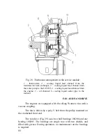
The engines are equipped with a turbocharger consisting of an
inward flow radial turbine and a centrifugal compressor with a
wastegate.
Summary of Contents for YMZ-536
Page 14: ...14 Fig 1 YMZ 536 engine right side view ...
Page 15: ...15 Fig 1 a YMZ 536 engine left side view ...
Page 16: ...16 Fig 1 b YMZ 536 10 engine right side view ...
Page 17: ...17 Fig 1 c YMZ 536 10 engine left side view ...
Page 18: ...18 Fig 1 d YMZ 536 30 engine right side view ...
Page 19: ...19 Fig 1 e YMZ 536 30 engine left side view ...
Page 20: ...20 Fig 1 f YMZ 5362 engine right side view ...
Page 21: ...21 Fig 1 g YMZ 5362 engine left side view ...
Page 22: ...22 Fig 1 h YMZ 53602 engine right side view ...
Page 23: ...23 Fig 1 i YMZ 53602 engine left side view ...
Page 51: ...51 Fig 10 Longitudinal section ...
Page 52: ...52 This page intentionally left blank ...
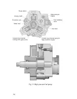
Page 96: ...96 Fig 33 High pressure fuel pump ...
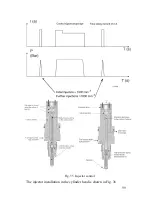
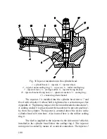
Page 99: ...99 Fig 35 Injector control The injector installation in the cylinder head is shown in Fig 36 ...
Page 168: ...168 NOTES ...

