26
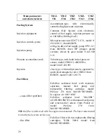
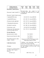
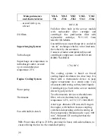
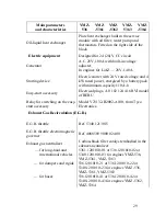
Main parameters
and characteristics
YMZ-
536
YMZ
-5361
YMZ
-5362
YMZ-
5363
YMZ
-5364
Fueling System
Accumulator-type, with electronically
controlled high pressure injection
Injection equipment
Common Rail System with electronic
control of fuel supply, injection pressure up
to 180 MPa (1800 kgf/cm
2
)
Injection control system
Microprocessor unit EDC7 UC31, model 0
281 020 111 from BOSCH,
Injection pump
with gear-driven fuel supply pump CPN 2.2+
from BOSCH, three HP plunger piston
sections, driven by gear; model 0 445 020
110.
Pressure accumulator (rail)
Tubular type, with built-in fuel pressure
sensor, model LWR N3, «BOSCH»,
model 0 445 226 091
Injectors
close type, with multijet nozzle, operated by
quick electromagnetic valve CRIN2 from
BOSCH, model 0 445 120 178
Fuel filters
– coarse filter (prefilter)
Full-flow sediment bowl with moisture
separator, manual feed pump and
replaceable filtering cartridge; model
PreLine 270 from MANN+HUMMEL.
In engines for OAO MAZ:
Full-flow sediment bowl “RACOR”
(4160YHH10MTC) with manual feed pump
and water-in-fuel sensor, from Parker or
model PreLine 270 from
MANN+HUMMEL.
NB: the filter is delivered with the engine not-mounted. The buyer must install
it into the fuel system on his own.
– fine filter
Full-flow filter with two replaceable filtering
cartridges, WDK 940/4 model from
MANN+HUMMEL.
Summary of Contents for YMZ-536
Page 14: ...14 Fig 1 YMZ 536 engine right side view ...
Page 15: ...15 Fig 1 a YMZ 536 engine left side view ...
Page 16: ...16 Fig 1 b YMZ 536 10 engine right side view ...
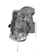
Page 17: ...17 Fig 1 c YMZ 536 10 engine left side view ...
Page 18: ...18 Fig 1 d YMZ 536 30 engine right side view ...
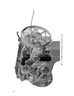
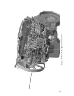
Page 19: ...19 Fig 1 e YMZ 536 30 engine left side view ...
Page 20: ...20 Fig 1 f YMZ 5362 engine right side view ...
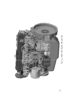
Page 21: ...21 Fig 1 g YMZ 5362 engine left side view ...
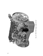
Page 22: ...22 Fig 1 h YMZ 53602 engine right side view ...
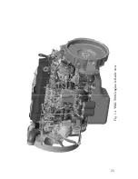
Page 23: ...23 Fig 1 i YMZ 53602 engine left side view ...
Page 51: ...51 Fig 10 Longitudinal section ...
Page 52: ...52 This page intentionally left blank ...
Page 96: ...96 Fig 33 High pressure fuel pump ...
Page 99: ...99 Fig 35 Injector control The injector installation in the cylinder head is shown in Fig 36 ...
Page 168: ...168 NOTES ...


