29
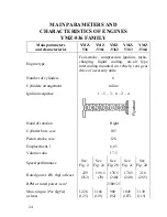
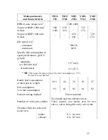
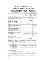
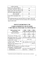
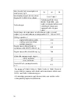
Main parameters
and characteristics
YMZ-
536
YMZ
-5361
YMZ
-5362
YMZ-
5363
YMZ
-5364
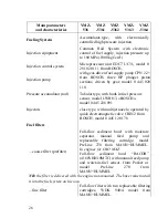
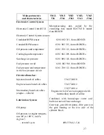
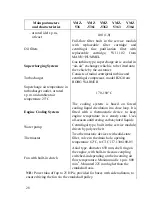
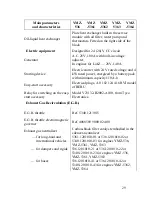
Oil-liquid heat exchanger
Plate heat exchanger built in the service
module with oil filter, water pump and
thermostats. Fitted on the right side of the
block.
Electric equipment
Designed for 24 (28) V CC circuit
Generator
A.C. 28V, 100A with built-in voltage
adjuster.
In engines for LiAZ — 28V, 140A.
Starting device
Electric starter with 24 V rated voltage and 4
kW rated power, energized by a battery pack
with minimum capacity 110 A-h
Easy-start accessory
Electrical plugs,
А
0 102 124 416 RVI model
of BERU
Relay for switching on the easy-
start accessory
Model V23132-B2002-A100, from Tyco
Electronics.
Exhaust Gas Recirculation (E.G.R.)
E.G.R. throttle
Ref. 5340.1213015
E.G.R. throttle electromagnetic
governer
Ref. 4088589 9000 024 00
Exhaust gas neutralizer
Carbon-black filter catalyst embodied in the
silencer-neutralizer
— for long-haul and
international vehicles
5361.1201010-01 or 536.1201010-02 or
5340.1201010-03 for engines YMZ-536,
YMZ-5361, YMZ-5363
— for dumpers and rigids 536.1201010-21 or 536.1201010-22 or
5340.1201010-23 for engines YMZ-536,
YMZ-5361, YMZ-5363
— for buses
536.1201010-41 or 536.1201010-42 or
5340.1201010-43 for engines YMZ-5362,
YMZ-5364
Summary of Contents for YMZ-536
Page 14: ...14 Fig 1 YMZ 536 engine right side view ...
Page 15: ...15 Fig 1 a YMZ 536 engine left side view ...
Page 16: ...16 Fig 1 b YMZ 536 10 engine right side view ...
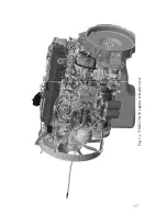
Page 17: ...17 Fig 1 c YMZ 536 10 engine left side view ...
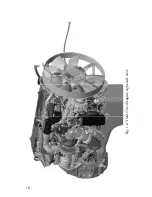
Page 18: ...18 Fig 1 d YMZ 536 30 engine right side view ...
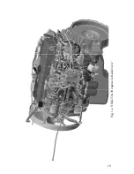
Page 19: ...19 Fig 1 e YMZ 536 30 engine left side view ...
Page 20: ...20 Fig 1 f YMZ 5362 engine right side view ...
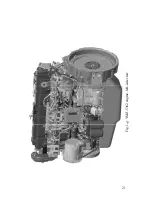
Page 21: ...21 Fig 1 g YMZ 5362 engine left side view ...
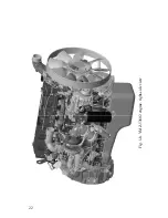
Page 22: ...22 Fig 1 h YMZ 53602 engine right side view ...
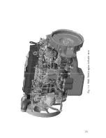
Page 23: ...23 Fig 1 i YMZ 53602 engine left side view ...
Page 51: ...51 Fig 10 Longitudinal section ...
Page 52: ...52 This page intentionally left blank ...
Page 96: ...96 Fig 33 High pressure fuel pump ...
Page 99: ...99 Fig 35 Injector control The injector installation in the cylinder head is shown in Fig 36 ...
Page 168: ...168 NOTES ...


