58
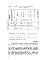
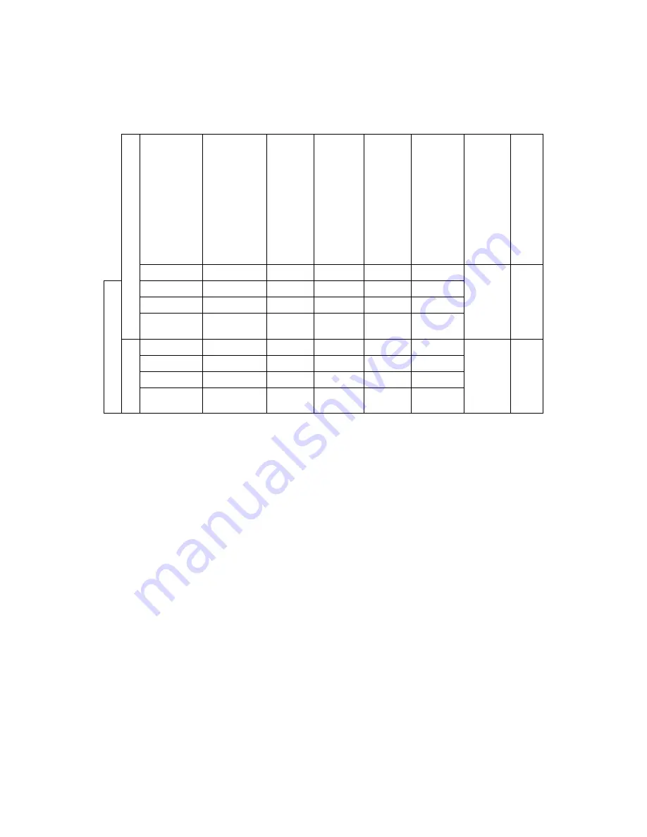
Table 1
Crankshaft journal sizes; Labeling on crankshaft,
journals and semi-rings
Main and a
dditional
designation
тельное
Crankshaft
Labeling
Crankpin
diame
ter, mm
Big end shell
Labeling
Main jour
nal
diame
ter, mm
Crankshaf
t bearing
liner Labeling
Trust jour
nal length,
mm
Semi-ring diame
ter
Main 00
76
-0,019
Std 88
-0,022
std
–
Ш
1 01
75,90
0,1
88,0
0,1
–
К
1 10
76,0
-
87,90
-
Manufac
ture
–
Ш
1
К
1 11 75,90
0,1
87,90
0,1
37
+0,062
std
2
d
repair 75,75
0,25
87,75
0,25
3
rd
repair
75,50 0,50 87,50 0,50
4
th
repair 75,25
0,75
87,25
0,75
Repair
5
th
repair
75,0
1
87,0
1
37,5
0,5
ATTENTION!
WHEN REGRINDING THE CRANKSHAFT
JOURNALS TO THE REPAIR DIMENSION, AVOID BURNS ON THE
JOURNALS, FILLETS AND ESPECIALLY WEB FACES!
UNREMOVED CRACKS WILL CAUSE SHAFT FAILURE. IF
PROPERLY OPERATED, THE CRANKSHAFT HAS A LIFE TIME
NOT LESS THAN THAT OF THE ENGINE.
FLYWHEEL
The flywheel is cast in grey cast iron. The steel ring gear press-
fitted onto the flywheel is used to start-up the engine with a starter.
The flywheel is manufactured for the size 430 clutch installed into the
SAE-1 housing. The flywheel is dynamically balanced separately
from the shaft. Installed into the mounting bore is the closed front
bearing of the gearbox primary shaft. To remove the flywheel, two
М
8 threaded holes are designed. The flywheel outer surface has 58
holes to control the engine performance, and the 1
st
cylinder TDC
mark. During installation the flywheel is oriented along a pin,
vertically, towards the 1
st
and the 6
th
cylinder TDC. From the clutch
Summary of Contents for YMZ-536
Page 14: ...14 Fig 1 YMZ 536 engine right side view ...
Page 15: ...15 Fig 1 a YMZ 536 engine left side view ...
Page 16: ...16 Fig 1 b YMZ 536 10 engine right side view ...
Page 17: ...17 Fig 1 c YMZ 536 10 engine left side view ...
Page 18: ...18 Fig 1 d YMZ 536 30 engine right side view ...
Page 19: ...19 Fig 1 e YMZ 536 30 engine left side view ...
Page 20: ...20 Fig 1 f YMZ 5362 engine right side view ...
Page 21: ...21 Fig 1 g YMZ 5362 engine left side view ...
Page 22: ...22 Fig 1 h YMZ 53602 engine right side view ...
Page 23: ...23 Fig 1 i YMZ 53602 engine left side view ...
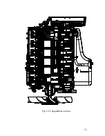
Page 51: ...51 Fig 10 Longitudinal section ...
Page 52: ...52 This page intentionally left blank ...
Page 96: ...96 Fig 33 High pressure fuel pump ...
Page 99: ...99 Fig 35 Injector control The injector installation in the cylinder head is shown in Fig 36 ...
Page 168: ...168 NOTES ...

