84
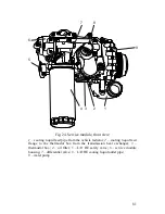
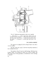
installed in the aluminum water pump housing
6
. The bearing is
closed and filled with grease.
On the pump drive spindle the end seal
9
is mounted and the
impeller
5
and the pulley
7
are press-fitted.
To ensure leak proofness of the end seal, the pump housing has
a drain hole
10
.
Installed on the suction cavity
2
is the cooling liquid feed pipe
from the vehicle radiator
1
.
From the volute cooling liquid comes to the L/O HE cavity
through the channel in the service module housing.
LIQUID-TO-OIL HEAT EXCHANGER
The liquid-to-oil heat exchanger (L/O HE) is used to maintain
optimal level of the oil temperature in the engine lubrication system.
The plate-type heat exchanger with one heat-transferring
element is part of the service module.
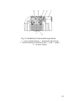
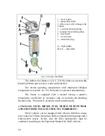
The plate-type heat-transferring element
2
(Fig.
26) with seven
plates is fixed onto the service module housing with four bolts
3
and
sealed against oil and cooling water leakage with a gasket
5
.
Summary of Contents for YMZ-536
Page 14: ...14 Fig 1 YMZ 536 engine right side view ...
Page 15: ...15 Fig 1 a YMZ 536 engine left side view ...
Page 16: ...16 Fig 1 b YMZ 536 10 engine right side view ...
Page 17: ...17 Fig 1 c YMZ 536 10 engine left side view ...
Page 18: ...18 Fig 1 d YMZ 536 30 engine right side view ...
Page 19: ...19 Fig 1 e YMZ 536 30 engine left side view ...
Page 20: ...20 Fig 1 f YMZ 5362 engine right side view ...
Page 21: ...21 Fig 1 g YMZ 5362 engine left side view ...
Page 22: ...22 Fig 1 h YMZ 53602 engine right side view ...
Page 23: ...23 Fig 1 i YMZ 53602 engine left side view ...
Page 51: ...51 Fig 10 Longitudinal section ...
Page 52: ...52 This page intentionally left blank ...
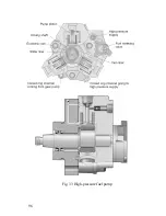
Page 96: ...96 Fig 33 High pressure fuel pump ...
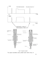
Page 99: ...99 Fig 35 Injector control The injector installation in the cylinder head is shown in Fig 36 ...
Page 168: ...168 NOTES ...

