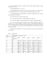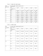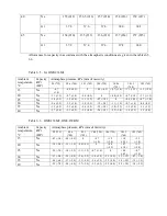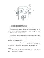
- to install and fasten the high-pressure fuel pump on the cylinder block;
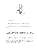
- to join and fasten using the bolts 5 the plates 4 of the drive coupling to the driven half-
coupling 2. Moment of force of the bolt tightening should be from 32 to 40 Nwm (from 3.2 to 4.0
kfg·m);
- rotating the crankshaft of the engine clock-wise if to look from the side of the fan drive, to
coincide the marking (groove) at the crankshaft pulley with the index marking at the distributor
timing cover corresponding adjustment angle of the lead of fuel injection for this model of the engine
or coincide the markings at the flywheel housing;
- to loose the tightening of the nuts 6 of the flange fastening 1 and to coincide the marking E at
the coupling of the lead injection with the marking Д at the indicator of the beginning of fuel feed
rotating the coupling clock-wise;
- to tighten the nuts 6 with the moment of force from 44 to 60 Nwm (from 4.4 to 6.0 kfg·m),
without changing the location of the coincided markings at the coupling of the lead injection and
indicator of the beginning of the fuel feed.
5.13 Installation of the water pump, by-pass pipes, tension machine and drive belt of the
water pump
5.13.1 Water pump gasket should be lubricated with the jointing compound
УН-25 from the
both sides.
5.13.2 Nuts of the fastening of the water pump should be tightened to the hard stop.
5.13.3 Installing the by-pass pipe filler ring which is installed in the water pump manifold and
pipe end joining with it should be lubricated with sealant Litol-24. By-pass pipe should be installed in
the manifold of the water pipe in the manifold ledge to the hard stop.
5.13.4 Bolts of the fastening of the tension mechanism at the water pump body should be tightened
with the moment of force from 80 to 110 Nwm (from 8.0 to11.0 kfg m).
5.13.5 Buckle of the drive belt of the water pump in the middle between the pulleys of the pump
and crankshaft while pressing of the belt with the force from 39.2 to 41.2 Nw (from 4.0 to 4.2
kfg) should be:
- from 7 to 12 mm – with the pump 236-1307010-
А3;
- from 10 to 12 mm – with the pump 236-1307010-
Б2. Belt tension is adjusted using:
- the pump 236-1307010-
А3 – changing of the quantity of adjusting gaskets installed between
the sides
of the pump pulley. At that dismounted gaskets should be installed at the outer side of the
external pulley side;
- the pump 236-1307010-
Б2 - rotating the lever of the support of the tension mechanism. After
the tension of the belt bolts of the fastening of the lever should be tightened with the moment of force
Summary of Contents for ???-236
Page 25: ...26...
Page 26: ...27 2...
Page 40: ......
Page 41: ......
Page 53: ......
Page 56: ......
Page 59: ......
Page 64: ...236 238 1003014 3 236 238 1003014 4 236 238 1003014...
Page 65: ......
Page 70: ......
Page 73: ......
Page 81: ......
Page 85: ......
Page 92: ......
Page 95: ......
Page 101: ......
Page 113: ......
Page 119: ......
Page 122: ......
Page 125: ......
Page 128: ......
Page 142: ......
Page 144: ......
Page 150: ......
Page 155: ......
Page 158: ......
Page 160: ......
Page 165: ......
Page 193: ...N u M a r Method defect detection and Dimension and parameter mm...
Page 201: ...4 Thread stripping M16 1 5 6H no more than two threads Inspection To calibrate the thread...


