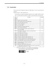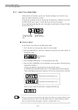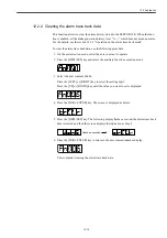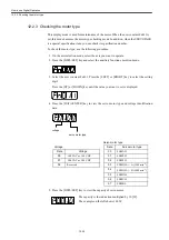
12.1 Basic operation
12-9
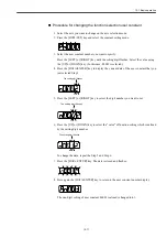
The user constant numbers which is not defined will be skipped during the operation.
User constant for function selection
Type of function selection user constant
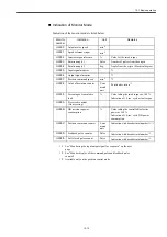
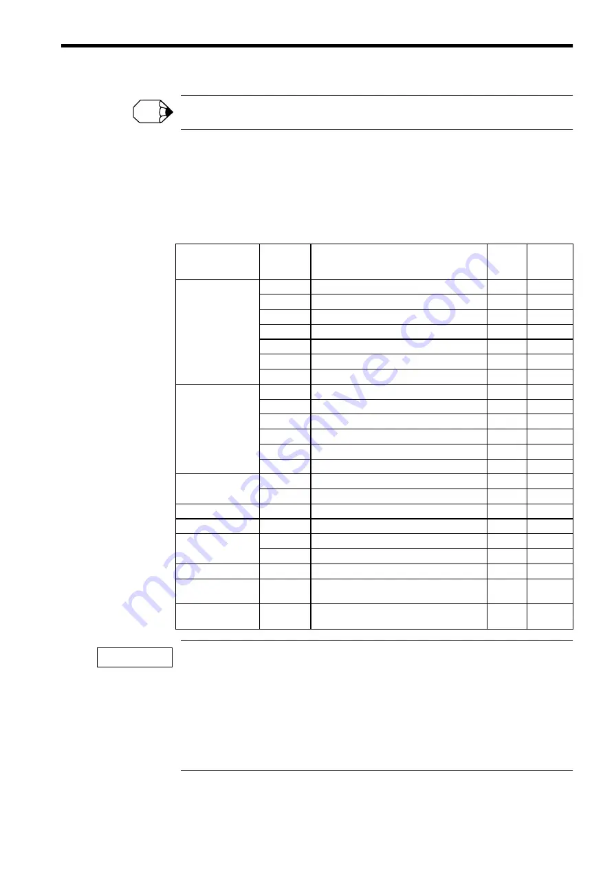
The following table lists the user constants used for selecting each function of SERVO-
PACK.
If you change the user constant that has a "
○
" in the remark column, you must cut off and then turn
on (or reclose) the power supply of both the main circuit and the control source in order to enable the
function of which setting you have just changed.
Also, some of the user constants that have an asterisk (*), such as Pn10B.1, Pn10B.3, Pn110.0,
Pn110.3, Pn127.0, and Pn408.2 requires the "reclosing the power supply" as shown above. On the con-
trary, Pn127.1 (Speed FF smoothing selection), Pn408.0 (1st stage notch filter selection) and Pn408.1
(2nd notch filter selection) can function on-line. Therefore they do not require the "recloseing the
power supply".
INFO
Type
User
constant
number
Name
Preset
value
Remarks
Constant for function
selection
Pn000
Function selection basic switch
0070
○
Pn001
Function selection application switch 1
0000
○
Pn002
Function selection application switch 2
0000
○
Pn003
Function selection application switch 3
0002
Pn004
Function selection application switch 4
0000
○
Pn005
Function selection application switch 5
0000
○
Pn006
Function selection application switch 6
0000
○
Constant for servo
gain
Pn10B
Gain application switch
0004
*
Pn110
On-line automatic tuning switch
0012
*
Pn126
Function switch 1
0000
○
Pn127
Function switch 2
0000
*
Pn128
Loop gain bank switch
0000
○
Pn131
Predictive control parameter switch
0000
○
Constant for Position
control
Pn200
Position control instruction type selection switch
0100
○
Pn207
Position control function switch
0000
○
Constant for toque
Pn408
Torque function switch
0000
*
Communication
Pn800
Communication control
0000
Constant for
sequence
Pn801
Soft limit selection switch
0000
Pn802
Command mask
0000
○
Monitor
Pn813
Option monitor
0010
Command
supplement
Pn816
Return to reference point direction
0000
Control function
selection
Pn81B
Model following control mask
0000
IMPORTANT
Summary of Contents for CNC Series
Page 1: ...Maintenance Manual Serviceman Handbook MANUAL No NCSIE SP02 19 Yaskawa Siemens CNC Series...
Page 26: ...Part 1 Hardware...
Page 38: ...System Configuration 1 2 3 Spindle motor designations 1 12...
Page 58: ...Installing the control panels 2 3 5 Installing lightning surge absorbers 2 20...
Page 62: ...Installing the motors 3 4...
Page 84: ...Connection method 4 3 2 Setting the rotary switches on the inverters and servo units 4 22...
Page 96: ...Part 2 Software...
Page 102: ...Software configuration 6 6...
Page 113: ...7 2 Network settings 7 11 8 Click on the radio button to the left of Specify an IP address...
Page 121: ...7 2 Network settings 7 19...
Page 122: ...Part 3 PLC...
Page 154: ...Part 4 Setting up and maintenance...
Page 160: ...Overview of System 10 1 2 Basic operation 10 6...
Page 204: ...How to use Digital Operation 12 2 9 Setting the password setting for write prohibit 12 32...
Page 327: ...Error and Troubleshooting 15 4...
Page 328: ...15 1 Errors without Alarm Display and Troubleshooting 15 5...
Page 329: ...Error and Troubleshooting 15 6...
Page 343: ...Maintenance and Check 16 3 3 Setting up Initializing Absolute encoder 16 14...


