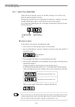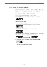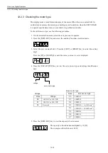
12.2 Application
12-17
12.2 Application
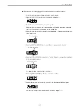
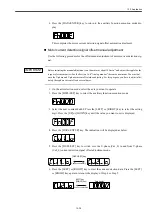
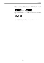
This section describes the application operation of digital operator in order to operate and adjust
the motor.
Read the section 12.1 "Basic operation" first.
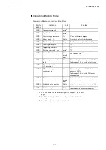
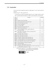
You can set the user constant for application operation on the "Auxiliary function execution
mode". The following table lists the user constants for auxiliary function execution mode.
Note: The user constants with a "
○
" mark and the user constants beginning
with "Pn" which have been set a password by Fn 010 are displayed as
followings. These user constants can not be changed.
User
constant
number
Function
Remarks
Fn000
Display of alarm trace back data
Fn001
Rigid setting at the time of on-line auto-tuning
○
Fn002
Reserved constant (no accessing)
Fn003
Origin searching mode
Fn004
(reserved constant)
Fn005
Initiation of user constant setting value
○
Fn006
Clear of alarm trace back data
○
Fn007
Inertia ratio from the result of on-line auto-tuning action
Write into EEPROM
○
Fn008
Multi return reset of absolute value encoder (setup operation)
and Alarm reset of encoder
○
Fn009
Reserved constant (no accessing)
○
Fn00A
Reserved constant (no accessing)
○
Fn00B
Reserved constant (no accessing)
○
Fn00C
Adjustment of analogue monitor output manual zero
○
Fn00D
Adjustment of analogue monitor output manual gain
○
Fn00E
Automatic adjustment of motor current detection signal offset
○
Fn00F
Manual adjustment of motor current detection signal offset
○
Fn010
Password setting (User constant rewrite prohibit)
Fn011
Check of motor type
Fn012
Indication of SERVOPACK soft ware version
Fn013
Setting changing of multi-return limit value at the time of the alarm "Multi-
return limit value mismatch (A.CC)" output
○
Flashes a
second.
Summary of Contents for CNC Series
Page 1: ...Maintenance Manual Serviceman Handbook MANUAL No NCSIE SP02 19 Yaskawa Siemens CNC Series...
Page 26: ...Part 1 Hardware...
Page 38: ...System Configuration 1 2 3 Spindle motor designations 1 12...
Page 58: ...Installing the control panels 2 3 5 Installing lightning surge absorbers 2 20...
Page 62: ...Installing the motors 3 4...
Page 84: ...Connection method 4 3 2 Setting the rotary switches on the inverters and servo units 4 22...
Page 96: ...Part 2 Software...
Page 102: ...Software configuration 6 6...
Page 113: ...7 2 Network settings 7 11 8 Click on the radio button to the left of Specify an IP address...
Page 121: ...7 2 Network settings 7 19...
Page 122: ...Part 3 PLC...
Page 154: ...Part 4 Setting up and maintenance...
Page 160: ...Overview of System 10 1 2 Basic operation 10 6...
Page 204: ...How to use Digital Operation 12 2 9 Setting the password setting for write prohibit 12 32...
Page 327: ...Error and Troubleshooting 15 4...
Page 328: ...15 1 Errors without Alarm Display and Troubleshooting 15 5...
Page 329: ...Error and Troubleshooting 15 6...
Page 343: ...Maintenance and Check 16 3 3 Setting up Initializing Absolute encoder 16 14...


