Drive set-up procedure
14.1.4 Axis configuration
14-10
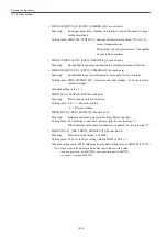
Parking setting (GAP axis setting)
When a drive is not used, the parking axis setting (GAPaxis setting) is required. For exam-
ple, in the case of that only one motor is connected to a 2-axis-combined drive.
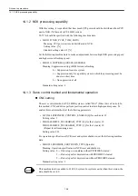
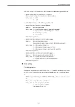
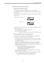
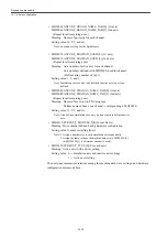
• MD3004 digit 2 (Pn004 digit 2) FUNCTION_SWITCH_APPLIC4 (For each axis) ##
Meaning: An axis is set as being a parking axis (GAP axis)
Setting value: 0 --- Active axis
2 --- Parking axis
Note: In case any setting error exists, the communication module LED of
the Converter lights up in Red; otherwise, it lights up in Green. You
cannot specify a Spindle as being a parking axis.
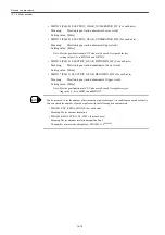
Hardware configuration using STEP7
This section summarizes precautions to be taken in performing a hardware configuration,
especially when you are using an SGDK drive. For how to use STEP 7 in detail, refer to
STEP7 manual.
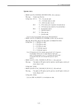
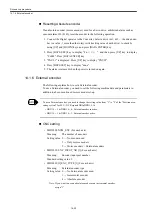
CNC, Converters, and drives connected to the Converters are to be set up. Up to 7 axes can
be connected to one Converter.
The following settings are to be made to the STEP7 for the GSD file of drive. As mentioned
above, you can connect up to 7 axes to one Converter and you can select either 2 ms or 4 ms
as a DP cycle.
• A portion that you need to set up: "Assigning Hexadecimal Parameters" of "DP Slave
Properties".
• A GSD file to be used is "YASK04E7".
• Setting descriptions: For a DP cycle of 2 ms or 4 ms, make the following settings:
In the case of 2 ms setting, the following setting (initial setting) can also be used.
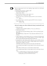
00,00,00,1C,E1,00,00,E1,00,00,5D,C0,00,01,01,00,00,0B,B8,00,03,00,07,00,00,17,70,00,
0A,00,00
For a logical address to be set using STEP7, set a value that matches with the following
machine data.
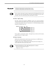
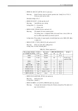
• MD1350 DRIVE_LOGIC_ADDRESS [n] (For each axis)
Meaning: Logical address of PROFIBUS for each drive
00,00,00,1C,E1,00,00,E1,00,00,17,70,00,04,01,00,00,0B,B8,00,03,00,07,00,00,17,70,00,0A,00,00
To --- For 2 ms setting: 00,07(1750us)
For 4 ms setting: 00,09(2250us)
Ti --- Always 00,03 (750us)
Tbase_io
‑‑‑
Always0B,B8 (250us)
Tdp
‑‑‑
For 2 ms setting: 00,04 (2ms)
For 4 ms setting: 00,08 (4ms)
Tbase_dp --- Always 17,70 (500us)
Summary of Contents for CNC Series
Page 1: ...Maintenance Manual Serviceman Handbook MANUAL No NCSIE SP02 19 Yaskawa Siemens CNC Series...
Page 26: ...Part 1 Hardware...
Page 38: ...System Configuration 1 2 3 Spindle motor designations 1 12...
Page 58: ...Installing the control panels 2 3 5 Installing lightning surge absorbers 2 20...
Page 62: ...Installing the motors 3 4...
Page 84: ...Connection method 4 3 2 Setting the rotary switches on the inverters and servo units 4 22...
Page 96: ...Part 2 Software...
Page 102: ...Software configuration 6 6...
Page 113: ...7 2 Network settings 7 11 8 Click on the radio button to the left of Specify an IP address...
Page 121: ...7 2 Network settings 7 19...
Page 122: ...Part 3 PLC...
Page 154: ...Part 4 Setting up and maintenance...
Page 160: ...Overview of System 10 1 2 Basic operation 10 6...
Page 204: ...How to use Digital Operation 12 2 9 Setting the password setting for write prohibit 12 32...
Page 327: ...Error and Troubleshooting 15 4...
Page 328: ...15 1 Errors without Alarm Display and Troubleshooting 15 5...
Page 329: ...Error and Troubleshooting 15 6...
Page 343: ...Maintenance and Check 16 3 3 Setting up Initializing Absolute encoder 16 14...


