14.1 Fundamental settings
14-23
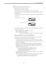
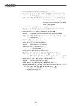
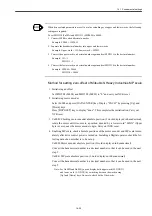
When a External encoder is connected for reverse rotation
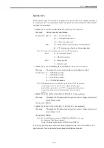
MD32100 (Motor encoder rotation direction), MD32110 (External encoder rotation direction), and
MD3002 digit 3 (External encoder rotation direction) are to be set as follows.
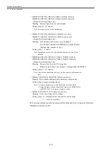
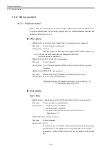
• MD3006 digit 2 (Pn006 digit 2) FUNCTION_SWITCH_APPLIC6 (For each axis)
Meaning: Full-closed
specification
Setting value: 0 --- Type 2 (Internal drive position feed-back is used as External encoder
pulse.)
1 --- Type 1 (Internal drive position feed-back is used as motor encoder
pulse.)
Standard setting value: 0
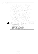
• MD3205 (Pn205) MULTI_TURN_LIMIT
Meaning:
Multi-turn limit setting
Setting value: Multi-turn limit setting of absolute motor encoder
When Mitsubishi Heavy Industries MP scale is used, assign a number, 1
less than the gear ratio between motor encoder and MP scale.
Note: If Servo drive alarm "204 (A.CC)" is displayed as a result of this
parameter setting, release it using Fn013 operation from the Digital
operator. (See INFO "
■
When multi-turn limit value inconsistency
happens" in 14.1.5.)
Since the Fn013 operation cannot be made to a 20-bit absolute
encoder, you cannot use a 20-bit absolute encoder in combination
with the MP scale.
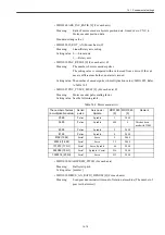
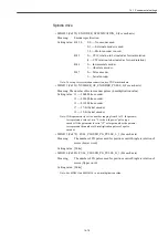
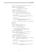
• MD3207 digit 3 (Pn207 digit 3) SWITCH_POSITION_REF (For each axis)
Meaning:
External PG type selection
Setting value: 0 --- Pulse encoder (Linear scale)
1 --- Pulse encoder (Rotary scale)
3 --- Mitsubishi Heavy Industries MP scale
Note: Be sure to assign "3" when an MP scale is used.
• MD3210 (Pn20A) PG_PLS_MTRRND_LW_FULLCLOSED (For each axis)
Meaning:
The number of full-closed PG pulses/Single revolution of motor (Lower
word)
Setting value: [Pulse]
INFO
External encoder
specification
Motor encoder
connection
Motor rotation
direction
MD32100
External encoder
rotation direction
MD32110
Motor rotation
encoder
MD3000 digit 0
External
encoder rotation
direction
MD3002 digit 3
Type 2 reverse
rotation
connection
Forward rotation
1
1
0
4 or 8
Reverse rotation
-1
1
0
2 or 6
Summary of Contents for CNC Series
Page 1: ...Maintenance Manual Serviceman Handbook MANUAL No NCSIE SP02 19 Yaskawa Siemens CNC Series...
Page 26: ...Part 1 Hardware...
Page 38: ...System Configuration 1 2 3 Spindle motor designations 1 12...
Page 58: ...Installing the control panels 2 3 5 Installing lightning surge absorbers 2 20...
Page 62: ...Installing the motors 3 4...
Page 84: ...Connection method 4 3 2 Setting the rotary switches on the inverters and servo units 4 22...
Page 96: ...Part 2 Software...
Page 102: ...Software configuration 6 6...
Page 113: ...7 2 Network settings 7 11 8 Click on the radio button to the left of Specify an IP address...
Page 121: ...7 2 Network settings 7 19...
Page 122: ...Part 3 PLC...
Page 154: ...Part 4 Setting up and maintenance...
Page 160: ...Overview of System 10 1 2 Basic operation 10 6...
Page 204: ...How to use Digital Operation 12 2 9 Setting the password setting for write prohibit 12 32...
Page 327: ...Error and Troubleshooting 15 4...
Page 328: ...15 1 Errors without Alarm Display and Troubleshooting 15 5...
Page 329: ...Error and Troubleshooting 15 6...
Page 343: ...Maintenance and Check 16 3 3 Setting up Initializing Absolute encoder 16 14...

