14.1 Fundamental settings
14-25
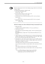
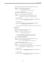
When drive-related parameters are set to a value extending over upper and lower words, the following
settings are required:
To set MD3210 (Pn20A) and MD3211 (MD20B) to 90000,
1. Convert 90000 to a hexadecimal number.
Example: 90000 = 15F90H
2. Separate the hexadecimal number into upper and lower words.
Example: Upper word = 1H; Lower word = 5F90H
3. Convert the upper word to a decimal number again and set MD3211 to the decimal number.
Example: 1H = 1
MD3211 = 1
4. Convert the lower word to a decimal number again and set MD3210 to the decimal number.
Example: 5F90H = 24464
MD3210 = 24464
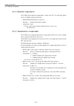
Method for setting zero offset of Mitsubishi Heavy Industries MP scale
1. Initializing an offset
Set MD3508 (Pn808) and MD3509 (Pn809) to "0" and carry out NCK reset.
2. Initializing motor encoder
Select Fn008 and press [DATA ENTER] key. Display "PGCL5" by pressing [Up] and
[Down] keys.
Press [DSPL/SET] key to display "done". This completes the initialization. Carry out
NCK reset.
3. Un00D: Checking motor encoder absolute position (2 words displayed in hexadecimal),
rotate the motor until it comes to a position denoted by a lower word "00XX" (Upper
byte is zero), near the motor encoder origin. Carry out NCK reset.
4. Enabling MP scale, check absolute positions of the motor encoder and MP scale imme-
diately after drive control power is turned on. Installing a Digital operator, check the fol-
lowing data of an axis that is to be set up.
Un00D: Motor encoder absolute position (2 words displayed in hexadecimal)
Convert the hexadecimal number to a decimal number so that it can be used in the next
step 5.
Un00E: MP scale absolute position (2 words displayed in hexadecimal)
Convert the hexadecimal number to a decimal number so that it can be used in the next
step 5.
Note: For Un00D and Un00E, you can display both upper word (H. XXXX)
and lower word (L. XXXX) by switching between the words using
[Up] and [Down] keys. Be sure to check both of the words.
INFO
Summary of Contents for CNC Series
Page 1: ...Maintenance Manual Serviceman Handbook MANUAL No NCSIE SP02 19 Yaskawa Siemens CNC Series...
Page 26: ...Part 1 Hardware...
Page 38: ...System Configuration 1 2 3 Spindle motor designations 1 12...
Page 58: ...Installing the control panels 2 3 5 Installing lightning surge absorbers 2 20...
Page 62: ...Installing the motors 3 4...
Page 84: ...Connection method 4 3 2 Setting the rotary switches on the inverters and servo units 4 22...
Page 96: ...Part 2 Software...
Page 102: ...Software configuration 6 6...
Page 113: ...7 2 Network settings 7 11 8 Click on the radio button to the left of Specify an IP address...
Page 121: ...7 2 Network settings 7 19...
Page 122: ...Part 3 PLC...
Page 154: ...Part 4 Setting up and maintenance...
Page 160: ...Overview of System 10 1 2 Basic operation 10 6...
Page 204: ...How to use Digital Operation 12 2 9 Setting the password setting for write prohibit 12 32...
Page 327: ...Error and Troubleshooting 15 4...
Page 328: ...15 1 Errors without Alarm Display and Troubleshooting 15 5...
Page 329: ...Error and Troubleshooting 15 6...
Page 343: ...Maintenance and Check 16 3 3 Setting up Initializing Absolute encoder 16 14...


