14-
106
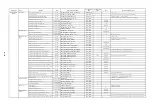
Main topic
Topic
Subtopic
Axis
Name of Machine Data
No. of Machine
data
Typical Setting
Value
UNIT
General setting and others
Moter control
(Cont’d)
Absolute value detec-
tion
(Cont’d)
Return to reference point status (motor encoder)
Feed
ENC_REFP_STATE[0]
MD34210
-
-
"2" at the reference setting completion
Return to reference point status (separately mounted encoder)
Feed
ENC_REFP_STATE[1]
MD34210
-
-
"2" at the reference setting completion
Motor encoder type
Feed
ENC_TYPE[0]
MD30240
-
-
"4" at the separately mounted encoder absolute value detection
Gantry control
Gantry axis setting
Feed
GANTRY_AXIS_TYPE
MD37100
-
-
Synchronicity warning output level position deviation
Feed
GANTRY_POS_TOL_WARNING
MD37110
-
mm,deg
Synchronicity alarm output level position deviation
Feed
GANTRY_POS_TOL_ERROR
MD37120
-
mm,deg
Return to reference point synchronicity deviation alarm output
level position deviation
Feed
GANTRY_POS_TOL_REF
MD37130
-
mm,deg
Gantry axis synchronization release
Feed
GANTRY_BREAK_UP
MD37140
-
-
0: Disabled 1:Synchlonization release Take notice when using this function.
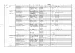
Spindle orientation
Feedforward mode
Spindle
FFW_MODE
MD32620
1
-
0: Disabled 1: Speed feedforward enabled Specify "1" for spindles.
Acceleration when the nth gear speed controlled
Spindle
GEAR_STEP_SPEEDCTRL_ACCEL[n]
MD35200
-
r/sec
2
Acceleration when the nth gear position controlled
Spindle
GEAR_STEP_POSCTRL_ACCEL[n]
MD35200
-
r/sec
2
Positioning control switching speed
Spindle
SPINDLE_POSCTRL_VELO
MD35300
-
min
-1
Rigid tap
Position loop gain when tap enabled
Feed
POSCTRL_GAIN[1]
MD32200
-
1/s
The nth gear spindle position loop gain
Spindle
POSCTRL_GAIN[n]
MD32200
-
1/s
n = 1 to 5
Threading
Acc./dec. motion when threading enabled
‑
THREAD_START_IS_HARD
MD20650
-
-
0: linear acc./dec. 1: Step acc./dec.
Spindle speed tolerance
Spindle
SPIND_DES_VELO_TOL
MD35150
-
-
Tolerance for speed reference
Acceleration when spindle speed controlled
Spindle
GEAR_STEP_SPEEDCTRL_ACCEL[n]
MD35200
-
r/sec
2
Threading acc./dec. distance
‑
THREAD_RAMP_DISP
SD42010
-
mm
Specify acc./dec. distance when the value is less than zero (0)
Spindle
synchronicity
control
Number of slave axis
Spindle
COUPLE_AXIS_1[0]
MD21300
-
-
Number of master axis
Spindle
COUPLE_AXIS_1[1]
MD21300
-
-
Spindle synchronicity mode
‑
COUPLING_MODE_1
MD21310
-
-
0: Feedback synchronicity 1: Position command synchronicity 2: Speed synchronicity
Block changing mode during synchronicity
‑
COUPLING_BLOCK_CHANGE_CTRL_1
MD21320
-
-
0: Immediate changing 1: Changing is enabled (Fine) 2:Changing is enabled (Coarse)
Synchronicity setting when reset
‑
COUPLING_RESET_MODE_1
MD21330
-
-
Synchronicity conditions adjustment setting
‑
COUPLING_IS_WRITE_PROT_1
MD21340
-
-
0: Program change available 1: Program change not available
Tolerance range for "Coarse synchronism"
‑
COUPLE_POS_TOL_COARSE
MD37200
-
mm,deg
Tolerance range for "Fine synchronism"
‑
COUPLE_POS_TOL_FINE
MD37200
-
mm,deg
Numerator for synchronous speed ratio
‑
COUPLE_RATIO[0]
SD42300
-
-
Denominator for synchronous speed ratio
‑
COUPLE_RATIO[1]
SD42300
-
-
Skip
Detection polarity for probe 1
Feed
MEAS_PROBE_LOW_ACTIVE[0]
MD13200
1
-
0: Positive 1: Negative
Detection polarity for prove 2
Feed
MEAS_PROBE_LOW_ACTIVE[1]
MD13200
1
-
0: Positive 1: Negative
Skip mode selection
Feed
MEAS_TYPE
MD13210
1
-
Specify "1" for drive latching
High-speed
high-accuracy
machining
Multi-block
look-ahead
Number of look-ahead blocks
‑
LOOKAH_NUM_CHECKED_BLOCKS
MD29000
100
-
Number of blocks used for look-ahead acc./dec. Use on G64 mode.
Block
compression
Compression position tolerance
‑
COMPRESS_POS_TOL
MD33100
-
mm
Block compression distance limiting value
‑
COMPRESS_BLOCK_PATH_LIMIT
MD20170
-
mm
Compression speed tolerance
‑
COMPRESS_VERO_TOL
MD20172
-
mm/min
Spline
compensation
Number of polynomial spline per block
‑
PATH_VELO_SEGMENTS
MD28530
5
-
Number of polynomial within a single spline curve
‑
ARCLENGTH_SEGMENTS
MD28540
10
-
Type of fine interpolation
‑
FIPO_TYPE
MD33000
2
-
1: Differential interpolation2: C spline interpolation
Summary of Contents for CNC Series
Page 1: ...Maintenance Manual Serviceman Handbook MANUAL No NCSIE SP02 19 Yaskawa Siemens CNC Series...
Page 26: ...Part 1 Hardware...
Page 38: ...System Configuration 1 2 3 Spindle motor designations 1 12...
Page 58: ...Installing the control panels 2 3 5 Installing lightning surge absorbers 2 20...
Page 62: ...Installing the motors 3 4...
Page 84: ...Connection method 4 3 2 Setting the rotary switches on the inverters and servo units 4 22...
Page 96: ...Part 2 Software...
Page 102: ...Software configuration 6 6...
Page 113: ...7 2 Network settings 7 11 8 Click on the radio button to the left of Specify an IP address...
Page 121: ...7 2 Network settings 7 19...
Page 122: ...Part 3 PLC...
Page 154: ...Part 4 Setting up and maintenance...
Page 160: ...Overview of System 10 1 2 Basic operation 10 6...
Page 204: ...How to use Digital Operation 12 2 9 Setting the password setting for write prohibit 12 32...
Page 327: ...Error and Troubleshooting 15 4...
Page 328: ...15 1 Errors without Alarm Display and Troubleshooting 15 5...
Page 329: ...Error and Troubleshooting 15 6...
Page 343: ...Maintenance and Check 16 3 3 Setting up Initializing Absolute encoder 16 14...


