14-
113
Hard ware
configuration
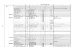
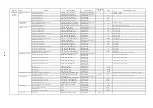
There occurs CNC alarm 25202 Axis waiting for drive or the LED lamp of PROFI-
BUS flashes.
The spindle is set as a parking axis.
It is impossible for the spindle to be a parking axis.
Set the spindle as an enabled axis. If there is no spindle motor, mask the motor and
encoder relevant alarm(s) with the spindle alarm mask.
14.1.4,14.1.8
The digital operation mode was once used.
The stand alone mode (digital operation mode) is enabled.
Release the stand alone mode.
14.1.3
There are connected multiple converters.
The station number of converter is wrong.
Check the station number of the converter.
Specify the station number which is not identical to any other converter station number but
suitable for the setting of hard ware configuration.
14.1.4
The parking axis was once enabled.
The parking axis setting (servo axis) is enabled.
Release the parking setting for the servo drive.
14.1.4
Encoder
There occurs CNC alarm 26002 Axis encoder N configuration error.
When power turned on.
The setting for the pulse number and type of CNC motor or separately mounted
encoder does not match that for the drive. (N = 1: Motor N = 2: Separately mounted
encoder)
Set the pulse number and type of CNC motor or separately mounted encoder to the setting
value matching the actual encoder pulse.
14.1.5
14.1.6
There occurs a servo drive alarm 129 (A:81:PG backup errors).
When power is turned on after the drive wiring is modi-
fied.
The backup value for the absolute value encoder is collapsed.
Reset the encoder.Reset the encoder.
14.1.5
When power is turned on.
The battery of converter is empty. The voltage is not high enough.
Attach a new normal battery.
There is no battery used since the absolute value
encoder is used as the incremental encoder.
Setting is not for the absolute value encoder to be used as the incremental encoder.
Set MD3002 digit 2 (Pn002 digit 2) = 1 in order to use the absolute value encoder as the
incremental encoder.
14.1.5
There occurs a servo drive alarm 204 (A.CC: multi-return limit value unmatched).
MD3205 (Pn205) has been modified.
The setting on the encoder side (Fn013) was not changed.
Modify the setting on the encoder side.
14.1.5
The multi-return limit value can not be changed.
A 20-bit encoder is used.
For the 20-bit encoder, the multi-turn limit value is unchangeable.
Set the setting value on the CNC-side multi-turn limit to the encoder value plus 1 (one) (=
65536).
14.1.5
With separately mounted encoder, there occurs position deviation in positioning
after the servo drive power is turned on/off.
MK scale is used.
The servo drive multi-return limit value setting error.
With 3205 (Pn205), set the value "-1" for the gear ratio of MP scale and motor encoder.
14.1.6
There occurs a servo drive alarm 203 (A.CB:PG echo back abnormal).
When control source is powered on.
The encoder cable is disconnected.
Properly connect the cable.
When the absolute value detection function is enabled, re-establish the origin.
Spindle
The rpm does not match the reference value.
When the speed reference operation is enabled.
The MD32260 setting value is wrong.
With MD32260, set the value of MD880.
14.1.7
The orientation speed fluctuates.
When the position control is started after the orientation
deceleration.
The speed feedforward for the spindle is not enabled.
Enable the spindle speed forward.
14.3.7,14.3.13
The spindle feedback signal display (rpm, speed waveform, etc.) flickers.
After the servo drive is powered on.
Since the resolution of spindle encoder is not high enough, the display flickers in the
range of encoder 1 pulse.
Set the low pass filter MD34990 for the spindle feedback.
14.2.2
There occurs CNC alarm 22051 at the orientation.
The first orientation after powered-on.
MD34060 REEP_MAX_MAPKER_DIST setting value is not large enough.
Set the value which is equal or exceed 360 deg.
14.3.5
Hard ware
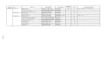
The LED lump of PROFIBUS lights, and there occurs the drive alarm 183 (B7: link
setting errors) and/or 230 (E6: network communication abnormal).
The control source is powered on.
The termination at the PROFIBUS terminal connector is not enabled.
Properly enabled the termination.
The LED lump of the servo/spindle drive RDY fails to light.
The control source is powered
The fuse of the control source is blown. This event often occurs when the connector of
control source is disconnected with the control source which is still powered on.
on.Inaccessible under the digital operation.
Replace the servo/spindle drive unit.
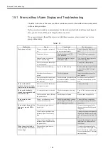
Category
Symptom
Conditions
Candidate causes
Measures
Remarks
(relevant sections)
Summary of Contents for CNC Series
Page 1: ...Maintenance Manual Serviceman Handbook MANUAL No NCSIE SP02 19 Yaskawa Siemens CNC Series...
Page 26: ...Part 1 Hardware...
Page 38: ...System Configuration 1 2 3 Spindle motor designations 1 12...
Page 58: ...Installing the control panels 2 3 5 Installing lightning surge absorbers 2 20...
Page 62: ...Installing the motors 3 4...
Page 84: ...Connection method 4 3 2 Setting the rotary switches on the inverters and servo units 4 22...
Page 96: ...Part 2 Software...
Page 102: ...Software configuration 6 6...
Page 113: ...7 2 Network settings 7 11 8 Click on the radio button to the left of Specify an IP address...
Page 121: ...7 2 Network settings 7 19...
Page 122: ...Part 3 PLC...
Page 154: ...Part 4 Setting up and maintenance...
Page 160: ...Overview of System 10 1 2 Basic operation 10 6...
Page 204: ...How to use Digital Operation 12 2 9 Setting the password setting for write prohibit 12 32...
Page 327: ...Error and Troubleshooting 15 4...
Page 328: ...15 1 Errors without Alarm Display and Troubleshooting 15 5...
Page 329: ...Error and Troubleshooting 15 6...
Page 343: ...Maintenance and Check 16 3 3 Setting up Initializing Absolute encoder 16 14...

