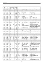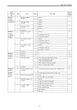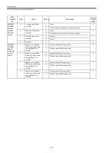
Drive data list
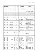
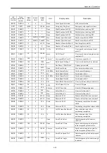
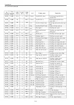
A.1 Servo unit parameter list
A-2
Appendix A Parameters
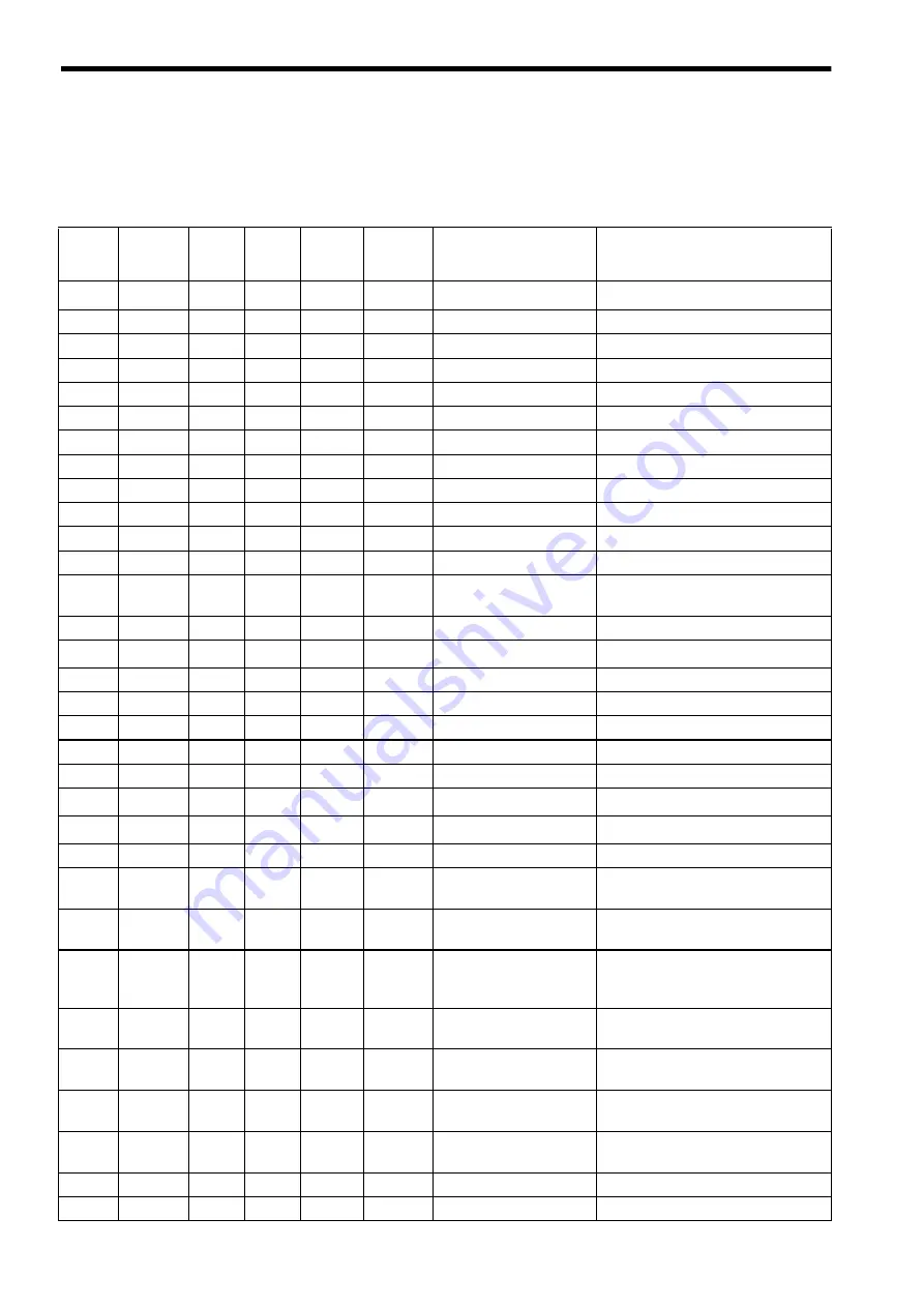
A.1 Servo unit parameter list
CNC
parameter
number
Drive
parameter
number
Initial
value
Lower
limit
Upper
limit
Unit
Display name
Description
3000
Pn000
0x0070 0x0000
0x0FA1
None
Function switch Basic
Fundamental function switch
3001
Pn001
0x0000 0x0000
0x0022
None
Function switch Applic 1
Applied function switch 1
3002
Pn002
0x0000 0x0000
0x8100
None
Function switch Applic 2
Applied function switch 2
3003
Pn003
0x0002 0x0000
0x4F4F
None
Function switch Applic 3
Applied function switch 3
3004
Pn004
0x0000 0x0000
0x0312
None
Function switch Applic 4
Applied function switch 4
3005
Pn005
0x0000 0x0000
0x0001
None
Function switch Applic 5
Applied function switch 5
3006
Pn006
0x0000 0x0000
0x0172
None
Function switch Applic 6
Applied function switch 6
3030
Pn100
400
10
20000
0.1Hz
Kv
Speed loop gain
3031
Pn101
2000
15
51200
0.01ms
Kvi
Speed loop integration time constant
3032
Pn102
400
10
20000
0.1/s
Kp
Position loop gain
3033
Pn103
0
0
10000
%
Load Inertia Ratio
Load inertia
3034
Pn104
400
10
20000
0.1Hz
Kv2
2nd speed loop gain
3035
Pn105
2000
15
51200
0.01ms
Kvi2
2nd speed loop integration time
constant
3036
Pn106
400
10
20000
0.1/s
Kp2
2nd position loop gain
3037
Pn107
0
0
450
min
-1
Bias
Bias
3038
Pn108
7
0
250
None
Bias Addition Width
Bias addition width
3039
Pn109
0
0
100
%
Feedforward
Feed forward
3040
Pn10A
0
0
6400
0.01ms
FF Filter Time Const
Feed forward filter time constant
3041
Pn10B
0x0004 0x0000
0x3014
None
Gain Switch
Gain-related applied switch
3042
Pn10C
200
0
800
%
Mode Switch Torque
Mode switch (Torque reference)
3043
Pn10D
0
0
10000
min
-1
Mode Switch Speed
Mode switch (Speed reference)
3044
Pn10E
0
0
3000
10min
-1
/s Mode Switch Accel
Mode switch (Acceleration)
3045
Pn10F
0
0
10000
None
Mode Switch Error Pulse
Mode switch (Deviation pulse)
3046
Pn110
0x0012 0x0000
0x2212
None
Switch Online Auto
Tuning
On-line auto tuning-related switch
3047
Pn111
100
1
500
%
Speed Feedback Comp
Gain
Speed feedback compensation gain
3048
Pn112
100
1
1000
%
Speed Feedback Delay
Comp
Speed feedback delay compensation
(Speed feedback compensation inertia
gain)
3049
Pn113
0
0
1000
%
Trq Dump Gain
AntiVibration
Anti-vibration torque damping gain
3050
Pn114
0
0
1000
%
Spd Dump Gain
AntiVibration
Anti-vibration speed damping gain
3051
Pn115
0
0
65535
0.01ms
LPF const AntiVibration
Anti-vibration low-pass filter time
constant
3052
Pn116
65535
0
65535
0.01ms
HPF const AntiVibration
Anti-vibration high-pass filter time
constant
3053
Pn117
100
20
100
%
Curr Gain delayed
Current loop gain derating
3054
Pn118
100
50
100
None
Reserved
Reserved const (Do not use)
Summary of Contents for CNC Series
Page 1: ...Maintenance Manual Serviceman Handbook MANUAL No NCSIE SP02 19 Yaskawa Siemens CNC Series...
Page 26: ...Part 1 Hardware...
Page 38: ...System Configuration 1 2 3 Spindle motor designations 1 12...
Page 58: ...Installing the control panels 2 3 5 Installing lightning surge absorbers 2 20...
Page 62: ...Installing the motors 3 4...
Page 84: ...Connection method 4 3 2 Setting the rotary switches on the inverters and servo units 4 22...
Page 96: ...Part 2 Software...
Page 102: ...Software configuration 6 6...
Page 113: ...7 2 Network settings 7 11 8 Click on the radio button to the left of Specify an IP address...
Page 121: ...7 2 Network settings 7 19...
Page 122: ...Part 3 PLC...
Page 154: ...Part 4 Setting up and maintenance...
Page 160: ...Overview of System 10 1 2 Basic operation 10 6...
Page 204: ...How to use Digital Operation 12 2 9 Setting the password setting for write prohibit 12 32...
Page 327: ...Error and Troubleshooting 15 4...
Page 328: ...15 1 Errors without Alarm Display and Troubleshooting 15 5...
Page 329: ...Error and Troubleshooting 15 6...
Page 343: ...Maintenance and Check 16 3 3 Setting up Initializing Absolute encoder 16 14...

