Appendix A Parameters
A-7
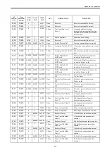
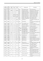
3424
Pn504
7
1
250
None
Near Window
NEAR signal width
3425
Pn505
1024
1
32767
None
Overflow Level
Overflow level
3426
Pn506
0
0
50
10ms
Delay from BrkSig to
SvOff
Brake command-to-Servo off delay
time
3427
Pn507
100
0
10000
min
-1
Spd on Brake Sig Out
Brake command output speed level
3428
Pn508
50
10
100
10ms
Sv Off Brk Sig Wait Time
Servo off-to-Brake command wait time
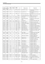
3429
Pn509
20
20
1000
None
Reserved
Reserved constant (Do not use)
3430
Pn50A
0x8880 0x7000
0x8FFF
None
Reserved
Reserved constant (Do not use)
3431
Pn50B
0x8888 0x7000
0x8FFF
None
Reserved
Reserved constant (Do not use)
3432
Pn50C
0x8888 0x0000
0xFFFF
None
Reserved
Reserved constant (Do not use)
3433
Pn50D
0x8888 0x0000
0xFFFF
None
Reserved
Reserved constant (Do not use)
3434
Pn50E
0x0000 0x0000
0xFFFF
None
Reserved
Reserved constant (Do not use)
3435
Pn50F
0x0000 0x0000
0xFFFF
None
Reserved
Reserved constant (Do not use)
3436
Pn510
0x0000 0x0000
0xFFFF
None
Reserved
Reserved constant (Do not use)
3437
Pn511
0x8888 0x0000
0xFFFF
None
Reserved
Reserved constant (Do not use)
3438
Pn512
0x0000 0x0000
0xFFFF
None
Reserved
Reserved constant (Do not use)
3439
Pn513
7
0
250
None
Position Window 1
1st positioning completion width
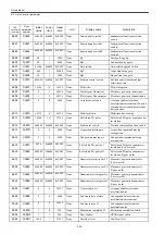
3440
Pn514
7
0
250
None
Position Window 2
2nd positioning completion width
3441
Pn515
7
0
250
None
Position Window 3
3rd positioning completion width
3442
Pn516
500
0
10000
ms
Emergency Stop Wait
Time
Emergency stop wait time
3470
Pn600
0
0
65535
None
Reserved
Reserved constant (Do not use)
3471
Pn601
0
0
65535
None
Reserved
Reserved constant (Do not use)
3472
Pn602
0x0000 0x0000
0x0001
None
Ext PG Power Switch
External PG power high/low voltage
switch
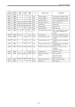
3508
Pn808
0x0000 0x0000
0xFFFF
None
Abs PG Zero Point Offs
LW
Absolute PG zero point offset
(Lower word)
3509
Pn809
0x0000 0x0000
0xFFFF
None
Abs PG Zero Point Offs
HW
Absolute PG zero point offset
(Upper word)
3510
Pn80A
100
1
65535
None
Const Linear Accel 1
1st-stage linear acceleration constant
3527
Pn81B
0x0000 0x0000
0x1111
None
Mask MFC BankSel 0 3
Model following control mask when
Loop gain bank 0-3 is selected.
3528
Pn81C
500
0
30000
ms
Tactor Off Delay Time
Time from tactor-off ready to actual
tactor-off.
CNC
parameter
number
Drive
parameter
number
Initial
value
Lower
limit
Upper
limit
Unit
Display name
Description
Summary of Contents for CNC Series
Page 1: ...Maintenance Manual Serviceman Handbook MANUAL No NCSIE SP02 19 Yaskawa Siemens CNC Series...
Page 26: ...Part 1 Hardware...
Page 38: ...System Configuration 1 2 3 Spindle motor designations 1 12...
Page 58: ...Installing the control panels 2 3 5 Installing lightning surge absorbers 2 20...
Page 62: ...Installing the motors 3 4...
Page 84: ...Connection method 4 3 2 Setting the rotary switches on the inverters and servo units 4 22...
Page 96: ...Part 2 Software...
Page 102: ...Software configuration 6 6...
Page 113: ...7 2 Network settings 7 11 8 Click on the radio button to the left of Specify an IP address...
Page 121: ...7 2 Network settings 7 19...
Page 122: ...Part 3 PLC...
Page 154: ...Part 4 Setting up and maintenance...
Page 160: ...Overview of System 10 1 2 Basic operation 10 6...
Page 204: ...How to use Digital Operation 12 2 9 Setting the password setting for write prohibit 12 32...
Page 327: ...Error and Troubleshooting 15 4...
Page 328: ...15 1 Errors without Alarm Display and Troubleshooting 15 5...
Page 329: ...Error and Troubleshooting 15 6...
Page 343: ...Maintenance and Check 16 3 3 Setting up Initializing Absolute encoder 16 14...

