Appendix A Parameters
A-13
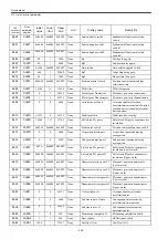
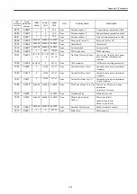
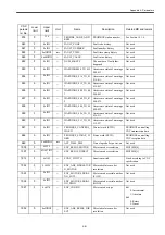
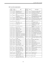
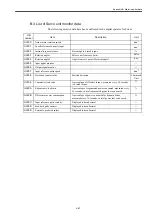
A.3 List of Inverter parameter
Note: The values shown in this table are based on the values shown in the
operator panel of the CNC. On the digital operator of the
SERVOPACK, the decimal point is displayed. In other words, the
unit for the value displayed on the operator panel is different from
the unit for the value on the digital operator.
When the zero speed detection level is set to 30 min
-1
, the displayed value are as follows.
MD6030: 300[0.1 min
-1
] on the operator panel of the CNC
Cn030:
30.0[min
-1
] on the digital operator of the SERVOPACK
EXAMPLE
CNC
paramete
r number
Drive
parameter
number
Initial
value
Lower
limit
Upper
limit
Unit
Display name
Description
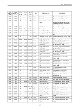
6020
Cn020
0
0
2
None
Reference Selection
Operation command selection
6030
Cn030
300
30
600
0.1min
-1
Zero-speed Det Level
Zero speed detection level
6031
Cn031
20
0
300
0.1min
-1
Zero-speed Det Width
Zero speed detection width
6032
Cn032
0
0
100
0.1sec
Zero-speed Braking Time
Zero speed braking time
6050
Cn050
1
1
60000
0.1sec
Soft Start Time
Soft start time
6060
Cn060
300
10
20000
0.1%/Hz
ASR P Gain H 1
Speed control proportional gain (H)
6061
Cn061
6000
1
10000
0.1msec
ASR I Time H 1
Speed control integration time (H)
6062
Cn062
300
10
20000
0.1%/Hz
ASR P Gain M L 1
Speed control proportional gain
(ML)
6063
Cn063
6000
1
10000
0.1msec
ASR I Time M L 1
Speed control integration time (ML)
6064
Cn064
400
10
20000
0.1%/Hz
ASR P Gain H 2
Speed control proportional gain (H
Servo)
6065
Cn065
1000
1
10000
0.1msec
ASR I Time H 2
Speed control integration time (H
Servo)
6066
Cn066
400
10
20000
0.1%/Hz
ASR P Gain M L 2
Speed control proportional gain (ML
Servo)
6067
Cn067
1000
1
10000
0.1msec
ASR I Time M L 2
Speed control integration time (ML
Servo)
6071
Cn071
50
0
50
0.1msec
ASR Primary Delay Time
Torque reference filter time constant
6072
Cn072
0
0
500
msec
ASR T Time
Torque reference lead time
6073
Cn073
0
0
1
None
ASR P Gain Select
Speed proportional gain selection
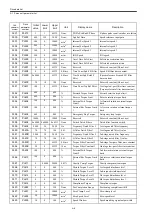
6100
Cn100
100
0
250
0.01
Torque Comp Gain
Torque compensation gain
6101
Cn101
20
0
10000
msec
Torque Comp Time
Constant
Torque compensation temporary
delay time
6110
Cn110
10
0
25
0.1
Slip Comp Gain
Slip correction gain
6111
Cn111
200
0
10000
msec
Slip Comp Delay Time
Slip correction temporary delay time
constant
6112
Cn112
200
0
250
%
Slip Comp Limit
Slip correction limit
6113
Cn113
0
0
1
None
Slip Comp in Regeneration
Slip correction during regeneration
operation
6120
Cn120
0
0
2
None
Carrier Frequency 1
High-speed winding carrier
frequency
6121
Cn121
0
0
2
None
Carrier Frequency 2
Low-speed winding carrier
frequency
6130
Cn130
1
0
1
None
Hunting Prevention Sel
Antihunting function selection
6131
Cn131
100
0
250
0.01
Hunting Prevention Gain
Antihunting gain
Summary of Contents for CNC Series
Page 1: ...Maintenance Manual Serviceman Handbook MANUAL No NCSIE SP02 19 Yaskawa Siemens CNC Series...
Page 26: ...Part 1 Hardware...
Page 38: ...System Configuration 1 2 3 Spindle motor designations 1 12...
Page 58: ...Installing the control panels 2 3 5 Installing lightning surge absorbers 2 20...
Page 62: ...Installing the motors 3 4...
Page 84: ...Connection method 4 3 2 Setting the rotary switches on the inverters and servo units 4 22...
Page 96: ...Part 2 Software...
Page 102: ...Software configuration 6 6...
Page 113: ...7 2 Network settings 7 11 8 Click on the radio button to the left of Specify an IP address...
Page 121: ...7 2 Network settings 7 19...
Page 122: ...Part 3 PLC...
Page 154: ...Part 4 Setting up and maintenance...
Page 160: ...Overview of System 10 1 2 Basic operation 10 6...
Page 204: ...How to use Digital Operation 12 2 9 Setting the password setting for write prohibit 12 32...
Page 327: ...Error and Troubleshooting 15 4...
Page 328: ...15 1 Errors without Alarm Display and Troubleshooting 15 5...
Page 329: ...Error and Troubleshooting 15 6...
Page 343: ...Maintenance and Check 16 3 3 Setting up Initializing Absolute encoder 16 14...

