Installing the control panels
2.1.1 Environmental conditions for installing the control panels and other system components
2-2
2.1 Designing the panels
2.1.1 Environmental conditions for installing the control panels and other
system components
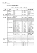
The operating temperature requirements for the YS 840DI system components are as fol-
lows:
If the operating temperature requirements were not observed, the performance could not be guaran-
teed.
The environmental requirements for the control panels are as follows:
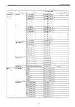
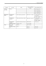
Table 2.1 Environmental requirements for the control panels and other system components
Function
Name
Allowable operating temperature
range
CNC unit
PCU50
5 - 45
℃
CNC operation panel (face)
OP010F
□
CNC operation panel (back)
Machine control panel
OP032S
0 - 45
℃
(face), 0 - 55
℃
(back)
Power supply module
PS module
0 - 60
℃
Power supply backup module
UPS module
Power supply backup battery
UPS battery
5 - 40
℃
Machine control panel I/O
PP module
0 - 55
℃
I/O power supply module
PS307
0 - 60
℃
(horizontal mounting),
0 - 40
℃
(vertical mounting)
Interface module
ET200M
I/O module
I/O module
SERVOPACK
SERVOPACK
0 - 55
℃
,
0 - 45
℃
(heat sink)
Reactor/winding changeover switch
Reactor
0 - 60
℃
Braking power supply unit
BK unit
0 - 60
℃
Items
Requirements
Ambient
temperature *1
During storage or transportation
-20 to +60
℃
During operation
5-30
℃
*2
Humidity
10-90% RH (with no dew)
Vibration and
shock
4.9 and 73.5 m/s
2
respectively
Atmosphere
Without excessive airborne dust, machining oil mist, or organic solvent vapor
Power supply
module, I/O power
supply module
100 - 230 VAC 50/60Hz
Power supply
Input supply voltage: 100/200 VAC; Frequency: 50/60 Hz
Converter
Main power supply
200-230 VAC +10/-15%, 50/60 Hz
±
5%, three-phase
Control power supply 200-230 VAC +10/-15%, 50/60 Hz
±
5%, single-phase
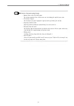
IMPORTANT
Env
iron
m
en
ta
l c
ond
iti
ons
Summary of Contents for CNC Series
Page 1: ...Maintenance Manual Serviceman Handbook MANUAL No NCSIE SP02 19 Yaskawa Siemens CNC Series...
Page 26: ...Part 1 Hardware...
Page 38: ...System Configuration 1 2 3 Spindle motor designations 1 12...
Page 58: ...Installing the control panels 2 3 5 Installing lightning surge absorbers 2 20...
Page 62: ...Installing the motors 3 4...
Page 84: ...Connection method 4 3 2 Setting the rotary switches on the inverters and servo units 4 22...
Page 96: ...Part 2 Software...
Page 102: ...Software configuration 6 6...
Page 113: ...7 2 Network settings 7 11 8 Click on the radio button to the left of Specify an IP address...
Page 121: ...7 2 Network settings 7 19...
Page 122: ...Part 3 PLC...
Page 154: ...Part 4 Setting up and maintenance...
Page 160: ...Overview of System 10 1 2 Basic operation 10 6...
Page 204: ...How to use Digital Operation 12 2 9 Setting the password setting for write prohibit 12 32...
Page 327: ...Error and Troubleshooting 15 4...
Page 328: ...15 1 Errors without Alarm Display and Troubleshooting 15 5...
Page 329: ...Error and Troubleshooting 15 6...
Page 343: ...Maintenance and Check 16 3 3 Setting up Initializing Absolute encoder 16 14...


