background image

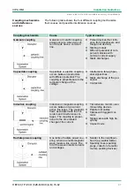
The following table shows the four different coupling mechanisms,

their causes and possible interference sources.

Coupling mechanism

Cause

Typical source

Galvanic coupling

Galvanic or metallic coupling

always occurs, when two cur-

rent circuits have a common

line.

n

Pulsed devices (Net influ-

ence from transducers and

foreign net devices)

n

Starting motors

n

Different potential of com-

ponent cubicles with

common current supply

n

Static discharges

Capacitate coupling

Capacitate or electric coupling

occurs between conductors

with different potential. The

coupling is proportionate to the

temporal change of the

voltage.

n

Interference through par-

allel signal lines

n

Static discharge of the per-

sonnel

n

Contactors

Inductive coupling

Inductive or magnetic coupling

occurs between two current

active line loops. The magnetic

flows associated with the cur-

rents induct interference vol-

tages. The coupling is propor-

tional to the time related

change of the current.

n

Transducers, motors, elec-

tric welding devices

n

Parallel net cables

n

Cables with toggled cur-

rents

n

Signal cable with high fre-

quency

n

Unused coils

Radiate power coupling

One talks of radiate power cou-

pling, when an electromagnetic

wave meets a line circuit. The

hit of the wave inducts currents

and voltages.

n

Sender in the neighbour-

hood (e.g. walkie-talkie)

n

Sparking lines (sparking

plugs, collector of electric

motors, welding devices)

Coupling mechanisms

and interference

sources

VIPA HMI

Installation Guidelines

Basic rules for the EMC-equitable assembly of installations

HB160 | TP-ECO | 62E-MDC0 | GB | 16-02


41

Summary of Contents for 62E-MDC0

Page 1: ...TP ECO 62E MDC0 Manual HB160 TP ECO 62E MDC0 GB 16 02 VIPA HMI Touch Panel TP604LC...

Page 2: ...62E MDC0_000_TP604LC 3 GB 2016 VIPA GmbH Ohmstr 4 91074 Herzogenaurach Telephone 49 9132 744 0 Fax 49 9132 744 1864 Email info vipa com Internet www vipa com...

Page 3: ...1 VIPA Startup Manager 23 3 4 Installation Movicon and Startup Manager 26 3 5 Connection to a PLC system 28 3 6 Operating system Windows Embedded CE 6 0 Core 29 3 6 1 General 29 3 6 2 Structure 31 3 7...

Page 4: ...om Every effort has been made to ensure that the information contained in this document was complete and accurate at the time of publishing Nevertheless the authors retain the right to modify the info...

Page 5: ...IPA GmbH Ohmstra e 4 91074 Herzogenaurach Germany Telefax 49 9132 744 1204 EMail documentation vipa de Contact your local VIPA Customer Service Organization representa tive if you encounter problems w...

Page 6: ...Safety information The Touch Panels are constructed and produced for n VIPA CPUs 01x 11x 21x 31x 51x and S7 300 400 from Sie mens n communication and process control n industrial applications n operat...

Page 7: ...carried out when the system has been disconnected from power Installation and hardware modifications only by prop erly trained personnel The national rules and regulations of the respective country mu...

Page 8: ...s that have been damaged by electrostatic discharges can fail after a temperature change mechanical shock or changes in the electrical load Only the conse quent implementation of protection devices an...

Page 9: ...rocess cycles n Windows CE 6 0 Core n Movicon 11 CE Basic 512 I O bytes n Processor ARM11 533MHz n Flash memory 128Mbyte RAM 128Mbyte n SD card slot n RS232 RS232 RS422 RS485 USB A and Ethernet interf...

Page 10: ...232 RS422 RS485 interface COM 2 4 Display with touch sensitive area touch screen 1 MPI PROFIBUS DP interface COM 3 optional 2 RS232 interface COM 1 1 RS232 RS422 RS485 interface COM 2 Front view Side...

Page 11: ...cation 3 Host USB A interface 4 Slot for DC 24V voltage supply Please make sure that the Touch Panel always has to be supplied with external voltage 2 3 2 Interfaces Back view VIPA HMI Hardware descri...

Page 12: ...25 pin SubD female RS232 RS422 RS485 interface VIPA HMI Hardware description Structure Interfaces HB160 TP ECO 62E MDC0 GB 16 02 12...

Page 13: ...quired for Ethernet Using the Host USB A interface USB mouse keyboard stick or USB hard discs can be connected The Touch Panel has got an integrated power supply The power supply has to be provided wi...

Page 14: ...ndows CE this memory is listed as Flashdisk at My Device The connection of USB sticks and USB drives by use of the Host USB A interface is supported by the Touch Panel After connection the storage med...

Page 15: ...y guaranteed when the following is observed Material thickness at the mounting cut out 2 5 6mm The deviation from the plane for the panel cut out is 0 5mm This condition must be fulfilled for the moun...

Page 16: ...process level electrically isolated Insulation resistance Insulation voltage to reference earth Inputs outputs AC DC 50V test voltage AC 500V Protective measures against short circuit Environmental c...

Page 17: ...V 80 AM 1kHz EN 61000 4 4 Burst degree of severity 3 EN 61000 4 5 Surge installation class 3 Due to the high energetic single pulses with Surge an appropriate external protective circuit with lightnin...

Page 18: ...xternal via USB Mouse external via USB Interfaces MPI PROFIBUS DP optional MPI PROFIBUS DP connector Serial COM1 RS232 COM1 connector Sub D 9 pin male Serial COM2 RS232 RS422 RS485 COM2 connector Sub...

Page 19: ...ting clips Protect type front side IP 65 Protect type back side IP 20 Dimensions Front panel 140 mm x 116 mm x 6 mm Rear panel 122 mm x 98 mm x 51 mm Installation cut out Width 123 mm Height 99 mm Min...

Page 20: ...the installation of the panel 4 mounting clips and a small hex agon socket key are required 1 Push the operator panel 3 from the front side into the front panel cutting 1 until it touches the panel wi...

Page 21: ...face module only at the holding plate and avoid touching the board Store respectively send the interface module always in the corresponding ESD packaging 1 Remove the cover plate of the COM3 port by r...

Page 22: ...is put into the right position by 2 inner guide rails 3 Now press the interface module downwards until the holding plate snaps into the lugs Please make sure that the holding plate always snaps to the...

Page 23: ...ation the device must be absolutely dry before connected to power To avoid overheat during operation the device must not be laid open to direct sun light After opening the control cabinet or desk ther...

Page 24: ...ated Here the MPI DP slave interface may also be configured Further you get here the Touch Panel information product number serial number and licenses To execute the firmware update press the button I...

Page 25: ...cribed After calibration tap any where at the screen The calibration window is closed 5 Via Start Settings Control Panel start the program AutoR unMaker Chapter 3 4 Installation Movicon and Startup Ma...

Page 26: ...o the select menu The VIPA Startup Manager will be closed by Exit and the system returns to the Windows screen With Back you get back to the start screen of the VIPA Startup Man ager 3 4 Installation...

Page 27: ...ur PC 4 Unzip the zip file and copy the file to the root directory of your SD card 5 Switch on the panel install the SD card and select via Start Settings Control Panel 6 Start in the Control Panel th...

Page 28: ...it to the Touch Panel via a connection that you ve entered before Via the at the Touch Panel pre installed run time version of the HMI SCADA project engineering platforms your project is run able By...

Page 29: ...is oper ating system Windows CE 6 0 Core is a Windows operating system reduced to the absolute essentials with mouse operation touch screen that requires only small hardware resources n ftp and VNC se...

Page 30: ...e drag ging that selects the touched objects The windows may be moved via the head bar Here you may also find the OK button to confirm entries and the X button for exiting the dialog You may not exit...

Page 31: ...Panel like e g applications system settings file browser etc 2 Open applications For every open application a button is to be found in the task bar There is no button for minimizing The switch betwee...

Page 32: ...ards are imple mented At pushed Shift key At pushed a key Please note that can exclusively be entered via the software keyboard Keyboard At pushed Shift key Software keyboard Keyboard Large KB VIPA HM...

Page 33: ...y the dialog win dows for the display properties opens Here you may change the settings for the monitor options For example you may adjust the brightness and contrast via the register Settings n Calib...

Page 34: ...l Panel Power Properties you may set the break time and the dimming of the back lighting For this choose AC Power at Power Scheme and then set the appro priate time A set suspend mode shuts down the T...

Page 35: ...a web server and receives an answer A server is an application that waits for the contact request of a client application and exchanges messages with it after contact start This communication type is...

Page 36: ...may monitor the IP address data via in the taskbar 4 After you ve confirmed the pre settings start your ftp client e g Windows Explorer and enter the following text into the address bar ftp wince vip...

Page 37: ...nc appears in the task bar You may also start the VNC server at the Touch Panel via a Telnet connection by entering the command winvnc in the command console with an active Telnet connection 3 Now sta...

Page 38: ...shared resources of the network PC test server To test the physical connection a PING to the IP address of the network PC may be executed if there are problems while contacting the network PC The conn...

Page 39: ...network printer The printer may now be accessed as network printer For example you may print the content of the current directory using dir network printer The listing command for all network connect...

Page 40: ...ronments and meets high demands on the EMC Neverthe less you should project an EMC planning before installing the compo nents and take conceivable interference causes into account Electromagnetic inte...

Page 41: ...he per sonnel n Contactors Inductive coupling Inductive or magnetic coupling occurs between two current active line loops The magnetic flows associated with the cur rents induct interference vol tages...

Page 42: ...with the cabinet Use metallic or metallised plug cases for isolated data lines n In special use cases you should appoint special EMC actions Consider to wire all inductivities with erase links Please...

Page 43: ...om corrosion e g with grease n Moveable grounding parts e g cubicle doors have to be con nected via flexible ground strips The ground strips should be short and have a large surface because the surfac...

Page 44: ...plicable lightning pro tection and grounding regulations when installing exterior cables CAUTION Where cables and signal lines for PLC equipment are installed outside of buildings the conditions for i...

Page 45: ...rrosion n The equipotential bonding conductor should be installed in such a manner that it includes the smallest surface between the bonding conductor and the signal lines Screening is one method comm...

Page 46: ...n n Attach the screens to the screening rail directly at the point where the cables enter the enclosure The screening conductor must be continued to the module without interruption however it must not...

Page 47: ...consist of incandescent lights e g LINESTRA lamps Avoid using fluorescent lamps as these lamps can cause interference If you can not avoid using fluorescent lamps you should implement the steps outlin...

Page 48: ...een grounded by means of grounding straps connected to the body of the cubicle Cable routing Cabling divided into groups Power cables 230 400V and signal lines installed in separate channels or bunche...

Reviews: