-
-
4
1.
RECEIVING
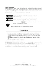
CAUTION
Verify that the product received is the product ordered.
Installing the wrong product may cause injury or equipment damage.
Check the following points although the product has been through strict inspections.
(1)
Check the nameplate to confirm that the product is as you ordered.
(2)
Check that there is no damaged part caused during transportation.
Contact your Yaskawa representative immediately if any failure should be found concerning the above items.
2.
INSTALLING TO INVERTER
(See Fig. 2.)
(1)
Turn OFF the main circuit power supply and remove the inverter front cover after passing the time
specified in the inverter front cover. Confirm that the CHARGE indicator lamp is extinguished.
(2)
Fit the SI-P1 card connector JP1 to the connector 2CN (number of pins: 60P) on the inverter control board.
At this time, insert the two SI-P1 card spacer mounting holes into the option card spacer on the control
board until a click is heard, and mount the SI-P1 card firmly. (See part in the side view.)
(3)
Connect the ground lead wire to the control circuit terminal E (For G5 inverter : terminal 12) of the inverter
control board.
(4)
After mounting the SI-P1 card, select the termination resistor, set the address switches 1 and 2, and make
connection with the card to the peripheral devices. After completion of connection, mount the inverter
front cover.
A
AUDIN - 7 bis rue de Tinqueux - 51100 Reims - France
Tel : 03.26.04.20.21 - Fax : 03.26.04.28.20 - Web : http: www.audin.fr - Email : info@audin.fr


